
LED backlight drive circuit and liquid crystal display

A technology of backlight driving circuit and LED lamp, applied in static indicators, instruments, light sources, etc., can solve the hidden dangers of system safety, increase the manufacturing cost of driving chips, sparks and other problems, and achieve the effect of reducing damage

Inactive Publication Date: 2017-05-31
TCL CHINA STAR OPTOELECTRONICS TECH CO LTD
View PDF5 Cites 1 Cited by
  • Summary
  • Abstract
  • Description
  • Claims
  • Application Information

AI Technical Summary

Problems solved by technology

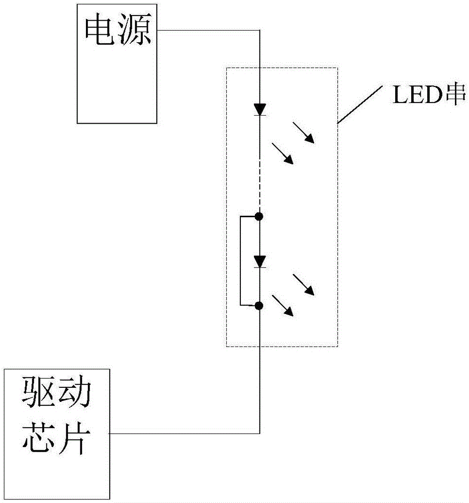
[0004] In the process of using the above-mentioned LED backlight driving circuit, the inventor of the present invention found that in the process of using the liquid crystal display, sometimes one end of the LED light (such as the + terminal) and the other end of the LED light (such as the - terminal) are short-circuited ( figure 1 Indicates that the two ends of the last LED are short-circuited), resulting in an increase in the voltage at the pin where the driver chip is electrically connected to the LED string, and this pin is a low-voltage pin, once the voltage at the pin is higher than the withstand voltage of the pin value, the pins of the driver chip will be broken down, resulting in damage to the driver chip, and even sparks in severe cases, which will bring hidden dangers to system safety
[0005] The existing technology provides two solutions, one of which is to build a high-voltage-resistant transistor at the pin of the driver chip, but this kind of solution is complicated in manufacturing process, which will increase the manufacturing cost of the driver chip; The pins of the chip have built-in low-voltage-resistant transistors. Although the manufacturing cost of this solution is low, when the voltage is higher than the withstand voltage of the transistors, the pins of the driver chip will be broken down, resulting in damage to the pins of the driver chip. ; so neither solution is ideal

Method used


Image

  • LED backlight drive circuit and liquid crystal display
  • LED backlight drive circuit and liquid crystal display
  • LED backlight drive circuit and liquid crystal display

Examples


no. 1 example

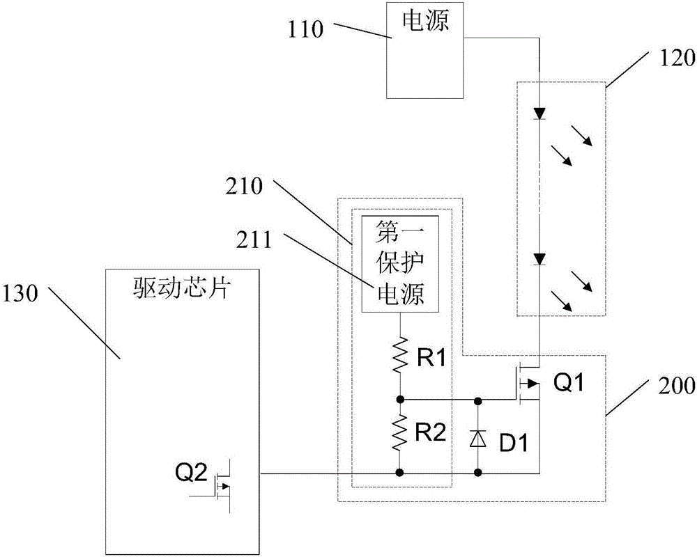
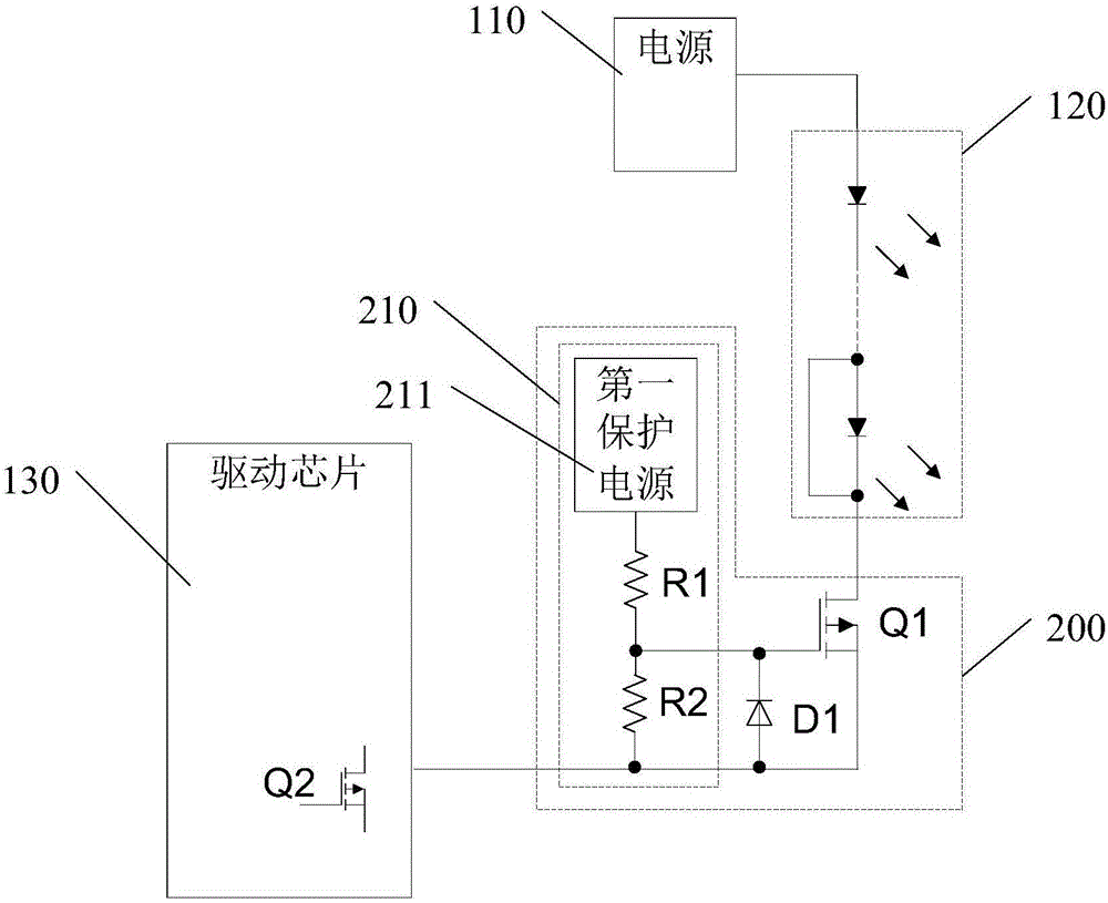
[0033] Please refer to figure 2 , is an LED backlight driving circuit provided in the first embodiment of the present invention, and the backlight driving circuit includes a power supply 110 , an LED string, a protection circuit and a driving chip 130 .

[0034] Specifically, the power supply 110 is used to provide power to the LED strings. The power supply 110 is, for example, a DC power output from other power supply circuits, or a DC power output from a power manager. The power supply provided in this embodiment 110 provides output voltages such as 36V (volts), 48V, 60V, 72V, etc., so as to drive LED strings.

[0035] The LED string includes a plurality of LED lamps, the positive end of the LED string is electrically connected to the power supply 110, the number of LED lamps in the LED string can be determined according to needs, for example, 2 LED lamps, 4 LED lamps, 6 LED lights, 8 LED lights, 9 LED lights, 10 LED lights, etc., the LED lights in the LED string can be co...

no. 2 example

[0046] Figure 4 The LED backlight drive circuit provided by the second embodiment of the present invention, Figure 4 circuit with figure 2 The circuits are similar, so the same component symbols represent the same components. The main difference between this embodiment and the first embodiment is the LED string and the protection circuit.

[0047] See Figure 4 , the LED string further includes a second LED string 320, the second LED string 320 includes a plurality of LED lamps connected in series, and the first LED string 120 and the second LED string 320 are connected in parallel. The positive end of the second LED string 320 is electrically connected to the power supply 110; the protection circuit also includes a second protection circuit 400, one end of the second protection circuit 400 is electrically connected to the negative end of the second LED string 320, and the second protection circuit The other end of 400 is electrically connected to the second pin of the d...


PUM


Abstract

The embodiment of the invention discloses an LED backlight drive circuit which comprises a power supply, an LED string, a protection circuit and a drive chip, wherein the LED string comprises a plurality of LED lamps; a positive end of the LED string is electrically connected with a power supply; one end of the protection circuit is electrically connected with a negative end of the LED string; a first pin of the drive chip is electrically connected with the other end of the protection circuit; when the LED string normally works, the protection circuit is conducted; when two ends of LED lamps in the LED sting are shorted, the protection circuit is automatically cut off to be used for protecting the drive chip. The embodiment of the invention further discloses the liquid crystal display. By adopting the LED backlight drive circuit and the liquid crystal display, the damage to the pin of the drive chip can be reduced.

Description

technical field [0001] The invention belongs to the technical field of liquid crystal display, and in particular relates to an LED backlight driving circuit and a liquid crystal display. Background technique [0002] With the continuous progress of display technology, the backlight technology of liquid crystal display has been continuously developed. Traditional LCD backlights use cold cathode fluorescent lamps (CCFL). However, due to the shortcomings of CCFL backlight such as poor color reproduction ability, low luminous efficiency, high discharge voltage, poor discharge characteristics at low temperature, and long time for heating to reach a stable gray level, LED (Light Emitting Diode, Chinese name: Light-emitting diode) backlight technology. [0003] figure 1 It is an existing LED backlight driving circuit for liquid crystal displays. like figure 1 As shown, the LED backlight driving circuit includes a power supply, an LED string and a driver chip. Specifically, the...

Claims


Application Information

Patent Timeline
Patent Type & Authority Applications(China)
IPC IPC(8): G09G3/34H05B44/00
CPCG09G3/3406G09G3/32G09G3/3648H05B45/46Y02B20/30H05B45/48H05B45/54
Inventor 李文东
Owner TCL CHINA STAR OPTOELECTRONICS TECH CO LTD
Learn More