
Wafer transfer device

A technology for transferring devices and wafers, used in transportation and packaging, electrical components, semiconductor/solid-state device manufacturing, etc. The effect of low intensity and ensuring continuity

Pending Publication Date: 2017-05-31
SHANGHAI SINYANG SEMICON MATERIALS
View PDF7 Cites 15 Cited by
  • Summary
  • Abstract
  • Description
  • Claims
  • Application Information

AI Technical Summary

Problems solved by technology

In the existing technology, relying on workers to manually transfer wafers is not only labor-intensive and inefficient, but also high in production costs, making it difficult to meet the needs of mass production

Method used


Image

  • Wafer transfer device

Examples


Embodiment Construction

[0028] The present invention will be described in detail below in conjunction with the accompanying drawings.

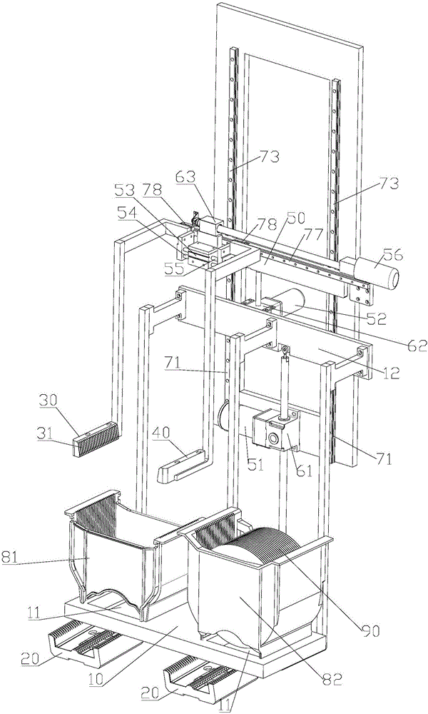
[0029] Such as figure 1 , a wafer transfer device, which includes a support table 10 , a tray 20 , a first robot arm 30 and a second robot arm 40 . The supporting platform 10 is provided with a plurality of through holes 11 . A plurality of through holes 11 are arranged at intervals. The supporting platform 10 is arranged on the bracket 12 . The bracket 12 can carry the supporting platform 10 and is set up and down. The first rotating motor 51 is connected to the first lead screw nut 61 , and the bracket 12 is connected to the first lead screw nut 61 . The first rotating motor 51 drives the bracket 12 to lift up and down through the first lead screw nut 61 . First sliders (not shown in the figure) are respectively arranged on the two first guide rails 71 . The first slider can lift and slide along the first guide rail 71 . The bracket 12 is connected with the ...


PUM


Abstract

The invention discloses a wafer transfer device which comprises a supporting table, a tray, a first mechanical arm and a second mechanical arm, wherein a through hole is formed in the supporting table, and the supporting table is arranged in a lifting manner; the tray is fixedly arranged under the supporting table, and runs through the through hole when the supporting table is lifted; the first mechanical arm and the second mechanical arm are arranged close to each other or far away from each other for commonly clamping a wafer; and the first mechanical arm and the second mechanical arm are arranged above the supporting table, can be lifted and are arranged in a horizontally moving manner. Since the wafer is taken and placed by utilizing fixing of the tray and lifting of the supporting table, the wafer transfer device has a high degree of automation, can be used for replacing manual wafer transfer, has small labor intensity and high efficiency, and can adapt to the requirement of large-scale production. The wafer transfer device can ensure stable operation of each part and protect the wafer from being damaged by utilizing a guiding device.

Description

technical field [0001] The invention relates to a wafer transfer device. Background technique [0002] During the wafer production process, various processing techniques are involved. Usually, for the needs of mass production, multiple wafers are placed in a magazine and processed at the same time. Cartridges require handling devices adapted to each process. However, in the actual production process, even for the same wafer cassette, the size of the cassette used in each processing step is different. Therefore, this determines the need to transfer wafers from one magazine to another during the entire processing process. In the prior art, relying on workers to manually transfer wafers is not only labor-intensive and inefficient, but also high in production costs, making it difficult to meet the needs of mass production. Contents of the invention [0003] The object of the present invention is to provide a wafer transfer device that can replace manual labor in order to o...

Claims


Application Information

Patent Timeline
Patent Type & Authority Applications(China)
IPC IPC(8): H01L21/677
CPCH01L21/67763H01L21/67766H01L21/67781
Inventor 王振荣黄春杰黄利松
Owner SHANGHAI SINYANG SEMICON MATERIALS
Learn More