Array substrate, manufacturing method thereof, and display device

A technology of an array substrate and a manufacturing method, applied in the field of display devices, can solve the problems of affecting picture quality, dim brightness, occupying pixel unit area, etc., and achieve the effects of improving picture quality, reducing brightness difference, and avoiding mutual interference

Active Publication Date: 2020-05-12
XIAMEN TIANMA MICRO ELECTRONICS
View PDF2 Cites 1 Cited by
  • Summary
  • Abstract
  • Description
  • Claims
  • Application Information

AI Technical Summary

Problems solved by technology

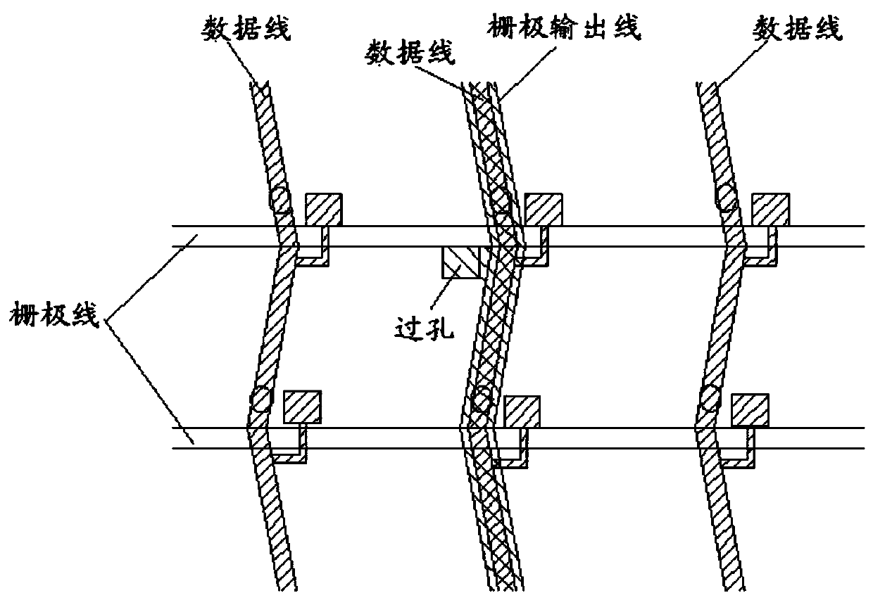
[0005] However, the inventors have found that although this arrangement method solves the above-mentioned bright spot problem, however, a certain amount of space must be required between the two data lines on the same layer and parallel to each other when the two data lines are arranged in the same wiring area. interval, the interval will undoubtedly occupy the area originally belonging to the pixel unit, and the pixel unit with reduced area will be darker in brightness compared with the normal pixel unit. Therefore, the above-mentioned improvement method in the prior art actually has an impact New problems with picture quality

Method used


Image

  • Array substrate, manufacturing method thereof, and display device
  • Array substrate, manufacturing method thereof, and display device
  • Array substrate, manufacturing method thereof, and display device

Examples


Embodiment Construction

[0057] Various exemplary embodiments of the present invention will now be described in detail with reference to the accompanying drawings. It should be noted that unless specifically stated otherwise, the relative arrangement of components and steps, numerical expressions and numerical values ​​set forth in these embodiments do not limit the scope of the present invention.

[0058] The following description of at least one exemplary embodiment is actually only illustrative, and in no way serves as any limitation to the present invention and its application or use.

[0059] The technologies, methods, and equipment known to those of ordinary skill in the relevant fields may not be discussed in detail, but where appropriate, the technologies, methods, and equipment should be regarded as part of the specification.

[0060] In all examples shown and discussed herein, any specific value should be interpreted as merely exemplary, rather than as a limitation. Therefore, other examples of th...


PUM


Abstract

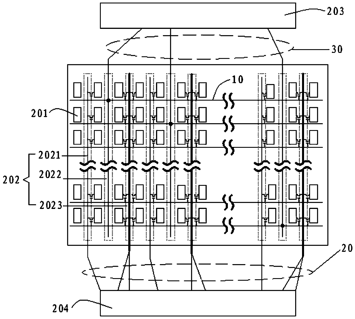
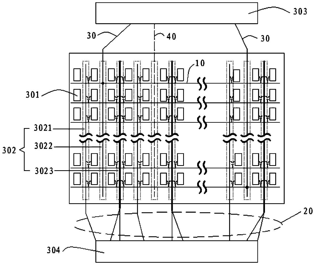
The invention discloses an array substrate and a manufacturing method of the array substrate as well as a display device. The array substrate comprises a pixel array composed of pixel units which are arrayed in a matrix manner, and a plurality of grid electrode wires which extend along the transverse direction of the pixel array; a routing region is arranged between every two adjacent rows of the pixel units; types of each routing region comprise a first routing region, a second routing region and a third routing region; each routing region is provided with a data line; at most one grid electrode output line is arranged in each second routing region, and is connected with the corresponding grid electrode line; each third routing region is provided with two data lines located on different thin film layers; the distance between the two data lines of each third routing region along the transverse direction of the pixel units is less than or equal to 0. According to the array substrate disclosed by the invention, the distance between the grid electrode output line and each data line can be increased, voltage coupling on the data lines is reduced, and the bright spot problem is solved; meanwhile, the distance between the two data lines of each third routing region is reduced, and influences on the picture quality effect can be weakened.

Description

Technical field [0001] The present invention relates to the field of display technology, and more specifically, to an array substrate, a manufacturing method of the array substrate, and a display device having the array substrate. Background technique [0002] Display devices with thin film transistors (TFTs) are now gradually becoming mainstream display devices. Each pixel on this type of display device is driven by a thin film transistor integrated behind the pixel. Specifically, the array substrate of this type of display device is also called a TFT substrate, including a pixel array, which is used to drive and control the gate lines, data lines, and gate output lines of each pixel in the pixel array. [0003] In the prior art, the gate lines of the array substrate are usually arranged along the direction of the pixel array row, and the data lines and the gate output lines are usually arranged along the direction of the pixel array column. The wiring diagram of the metal line is...

Claims


Application Information

Patent Timeline
Patent Type & Authority Patents(China)
IPC IPC(8): H01L27/12H01L21/77
CPCH01L27/124H01L27/1259
Inventor 许喜爱刘冰萍周秀峰蔡寿金
Owner XIAMEN TIANMA MICRO ELECTRONICS
Why Eureka
Try Eureka