Double-spiral-arm type luneberg lens antenna

A technology of Lunbo lens antenna and Lunbo lens, applied in the direction of antenna, antenna grounding switch structure connection, electrical components, etc., can solve the problems of complicated cable layout, easy misalignment of the center of the circle, and complicated feed source drive, etc. Compression bending, fast response, to achieve the effect of response

Pending Publication Date: 2017-05-31
NO 54 INST OF CHINA ELECTRONICS SCI & TECH GRP
View PDF5 Cites 15 Cited by
  • Summary
  • Abstract
  • Description
  • Claims
  • Application Information

AI Technical Summary

Problems solved by technology

[0007] The present invention discloses a Luneberg lens antenna with double helical arms in a new driving mode in order to solve the above-mentioned problem that the pointing accuracy of the existing Lu

Method used


Image

  • Double-spiral-arm type luneberg lens antenna
  • Double-spiral-arm type luneberg lens antenna
  • Double-spiral-arm type luneberg lens antenna

Examples


Embodiment Construction

[0025] combine Figure 1 to Figure 4 The present invention is described further:

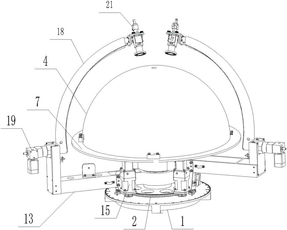
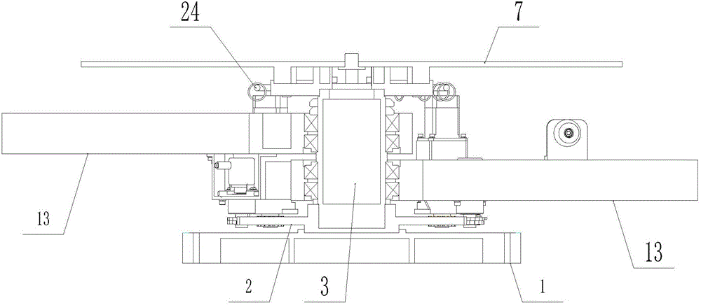
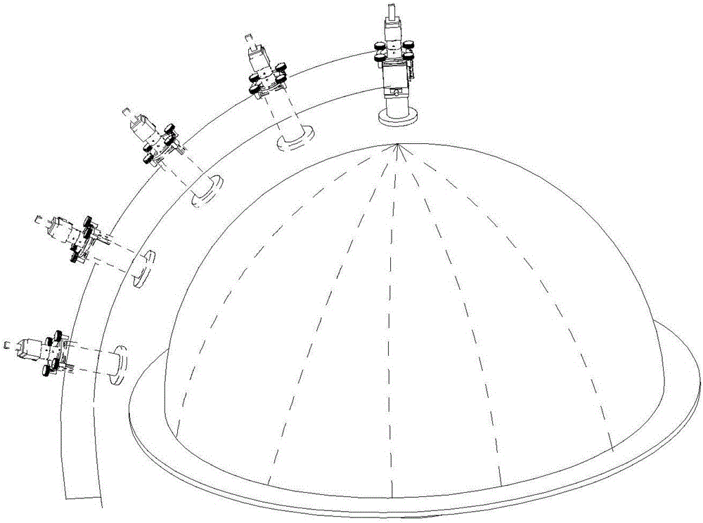
[0026] like figure 1 and figure 2 Shown: provide a kind of double helical arm type Luneberg lens antenna, it comprises base 1, lens reflection surface 7, Luneburg lens 4, described base is provided with support shaft 3, and lens reflection surface 7 is arranged on On the upper end of the support shaft, the Lunber lens 4 is mounted on the lens reflection surface 7, and the tooth disc 2 is coaxially fixed at the support shaft of the base, and two pointing and positioning devices are equipped on the support shaft of the base, located at A routing ring 24 is arranged above the pointing and positioning device on the supporting shaft, and a plurality of supporting rings are set on the routing ring.

[0027] like figure 1 As shown, each pointing and positioning device includes a bending arm 13 coaxially fitted on the supporting shaft, a tapered roller bearing is installed between the bending arm a...


PUM


Abstract

The invention discloses a double-spiral-arm type luneberg lens antenna, which comprises a base, a lens reflection face and a luneberg lens, wherein a supporting shaft is arranged on the base, the lens reflection face is arranged at the upper end of the supporting shaft, the luneberg lens is arranged on the lens reflection face, a fluted disk is coaxially fixed to the position of the supporting shaft of the base, a plurality of pointing location devices are arranged on the supporting shaft of the base, each pointing location device comprises a horizontal supporting arm which is coaxially arranged on the supporting shaft, a first rotary motor is fixed to each horizontal supporting arm, a gear arranged on an output shaft of each first rotary motor is meshed with the fluted disk, an arc spiral arm is pivoted to each horizontal supporting arm, the spiral arm upwards extends in an arc mode along an outer arc of the luneberg lens, a pivot shaft of each spiral arm and the lens reflection face are arranged on the same horizontal plane, a second rotary motor is arranged on the pivot shaft of each spiral arm, a feedback source is arranged at the top end of each spiral arm, the feedback sources point at the circle center of the luneberg lens, and orientation and angle adjustment of the feedback source devices are achieved through rotation of the double supporting arms. The antenna is simple in structure, and feedback source location is stable and reliable.

Description

technical field [0001] The invention relates to the technical field of antennas, in particular to a double-swivel Luneberg lens antenna. Background technique [0002] The Lunberg lens antenna is a spherical layered dielectric lens antenna. Compared with the parabolic antenna, its main feature is that it can focus the incident wave to a point on the spherical surface, and the multi-beam gain is consistent. At the same time, its own spherical symmetry and Good dielectric performance makes it have the advantages of multi-beam, wide frequency band, and wide scanning angle range, so it has been widely used in satellite communication, navigation, radar technology and other fields. [0003] For the Luneberg lens antenna in the form of dual feeds, the positioning method of the dual feeds is an important content of the antenna design. The existing dual-feed Luneberg lens antenna is a slideway configuration, and the movement mode of the feed source is an arc slideway type. In order ...

Claims


Application Information

Patent Timeline
IPC IPC(8): H01Q3/14H01Q3/18H01Q1/50
CPCH01Q1/50H01Q3/14H01Q3/18
Inventor 宋建虎杨晓琦李建军李勇郝会乾杨文宁贾彦辉
Owner NO 54 INST OF CHINA ELECTRONICS SCI & TECH GRP
Why Eureka
Try Eureka