
Serial port line capable of switching between cross connection and direct connection

A serial port line and direct connection technology, which is applied in the field of crossover direct switchable switch serial line, can solve the problems of unfavorable serial port signal and large contact resistance, and achieve the effect of saving research time and improving debugging efficiency

Active Publication Date: 2017-05-31
GUILIN UNIV OF ELECTRONIC TECH
View PDF13 Cites 1 Cited by
  • Summary
  • Abstract
  • Description
  • Claims
  • Application Information

AI Technical Summary

Problems solved by technology

[0005] For the double-pole double-throw switch described in "Serial Port Direct Connection and Crossover Line Switching Device", the contact of the switch is a point contact, and the contact resistance is relatively large, which is not good for processing weak serial port signals.

Method used


Image

  • Serial port line capable of switching between cross connection and direct connection
  • Serial port line capable of switching between cross connection and direct connection
  • Serial port line capable of switching between cross connection and direct connection

Examples


Embodiment Construction

[0030] The technical solutions of the present invention will be further described below in conjunction with the embodiments shown in the accompanying drawings.

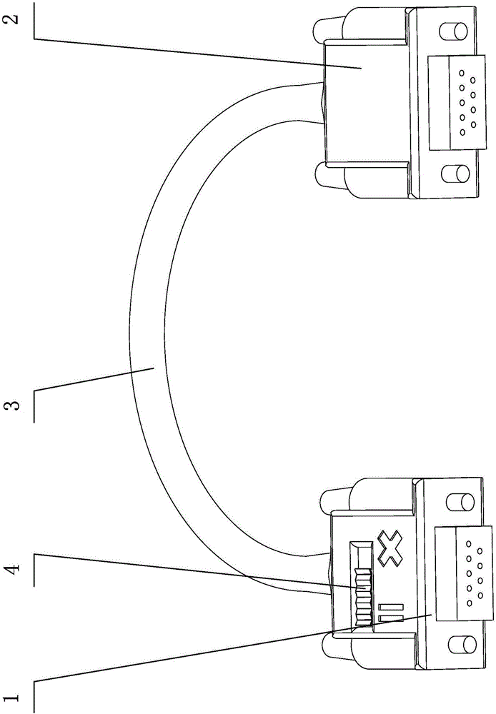
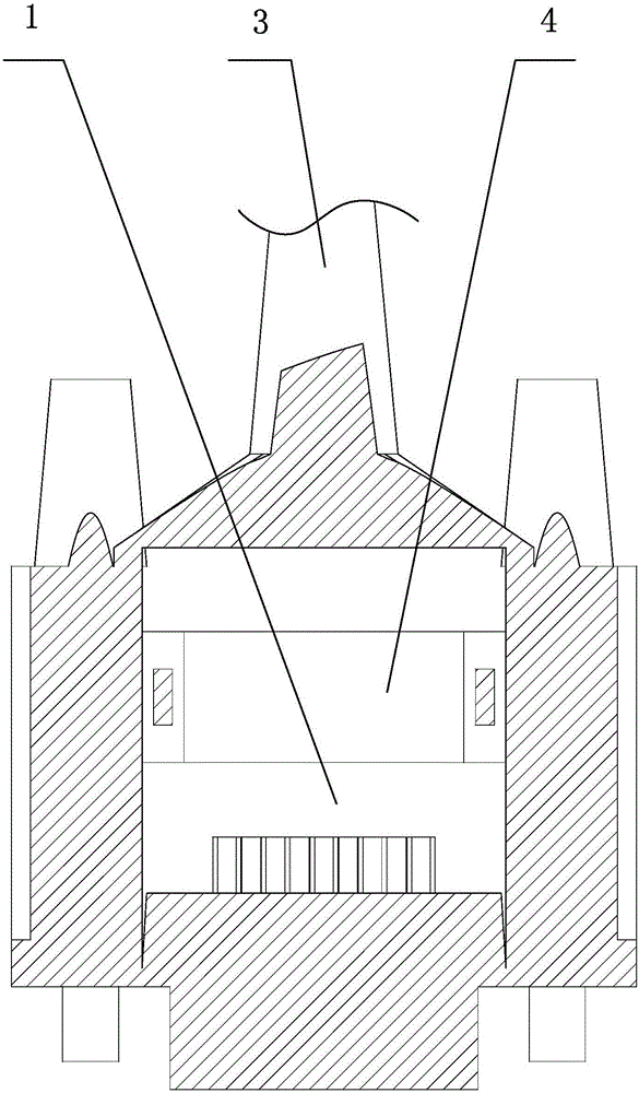
[0031] The crossover direct-connect switchable serial port line of the present invention includes a signal input serial port port 1 and a signal output serial port port port 2, and the signal input serial port port 1 and the signal output serial port port 2 are connected by a data line 3 to transmit signals, The signal input serial port terminal 1 is provided with a 4-pin 2-way 2-speed crossover direct connection switch 4, such as figure 1 shown.

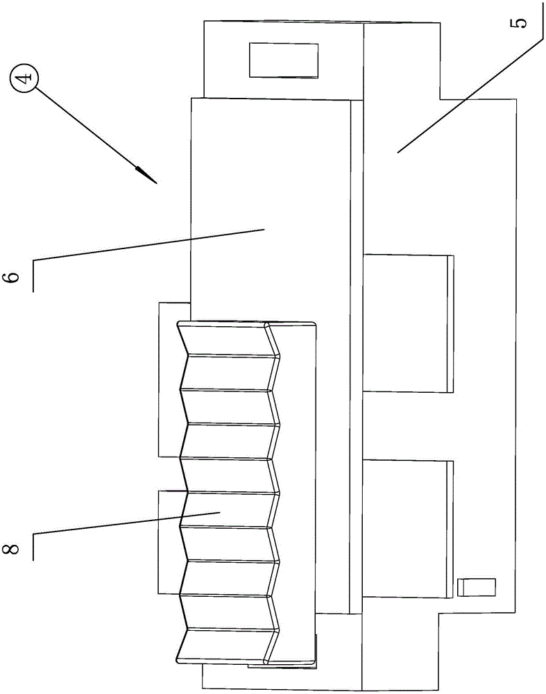
[0032] The crossover direct connection switch 4 is arranged left and right, and its structure includes a switch box 5, a switch cover 6, a sliding control block 7 and a signal transmission component, wherein,

[0033] The switch box 5 is placed inside the signal input serial port terminal 1, and there are left and right sliding chambers 5-1 inside the switch box 5, and the...


PUM


Abstract

The invention discloses a switching serial port line capable of switching between cross connection and direct connection. The switching serial port line capable of switching between the cross connection and the direct connection comprises a signal input serial port end and a signal output serial port end, wherein a cross connection and direct connection switching switch is arranged on the signal input serial port end; a sliding control block is arranged inside a sliding cavity of a switch box in a left-and-right sliding manner; a front signal transmitting assembly and a back signal transmitting assembly are arranged between the sliding control block and the front sliding surface of the switch box and between the sliding control block and the back sliding surface of the switch box respectively; the front signal transmitting assembly comprises an upper front elastic plate and a lower front elastic plate which are arranged on the sliding control block, and an upper front contact plate and a lower front contact plate which are arranged on the switch box; the upper front contact plate and the lower front contact plate are connected with an RXD and a TXD of the signal input serial port end respectively; the back signal transmitting assembly comprises an upper elastic plate and a lower elastic plate which are arranged on the sliding control block, and an upper back contact plate, a lower back contact plate, a left back contact plate and a right back contact plate which are arranged on the switch box; every two back contact plates are communicated in a cross way and are connected with the an RXD and a TXD of the signal output serial port end respectively. The switching serial port line capable of switching between the cross connection and the direct connection can switch between two states, namely a cross-connection line and a direct-connection line, on one serial port line, so that the development time of a researcher is saved and the product debugging efficiency is improved.

Description

technical field [0001] The invention relates to electrical components, in particular to a crossover direct-connect switch serial port line. Background technique [0002] Serial lines are widely used in electrical design, mainly for signal transmission. [0003] The existing serial lines are distinguished functionally, mainly including straight line and crossover line, but there is almost no difference in the appearance of these two types of serial lines, and there is no special mark for type distinction. bring inconvenience. [0004] For this reason, Patent No. 201420477556.5 discloses a "switching device for serial port direct connection line and crossover line". This realizes the function of direct connection and cross switching of serial port lines. [0005] For the double-pole, double-throw switch described in "Serial Port Direct Connection and Crossover Line Switching Device", the contacts of the switch are point contacts, and the contact resistance is relatively lar...

Claims


Application Information

Patent Timeline
Patent Type & Authority Applications(China)
IPC IPC(8): H01R31/06H01R13/46H01R13/70
CPCH01R13/465H01R13/70H01R31/06
Inventor 黄用华王昌盛张杰庄未匡兵黄美发孙永厚宋宜梅钟永全
Owner GUILIN UNIV OF ELECTRONIC TECH
Learn More