Distribution box with high heat dissipation performance and rainproof performance

A high heat dissipation and distribution box technology, applied in substation/power distribution device shell, electrical components, substation/switch layout details, etc., can solve the problem of poor heat dissipation of distribution box, and it may be burned if it is not dissipated in time , to achieve the effect of high heat dissipation performance

Active Publication Date: 2017-05-31
黑龙江省一滴水环保科技有限公司
View PDF5 Cites 28 Cited by
  • Summary
  • Abstract
  • Description
  • Claims
  • Application Information

AI Technical Summary

Problems solved by technology

[0002] Distribution box is assembled in closed or semiclosed metal safe by electrical wiring requirement by switchgear, measuring instrument, protective device and auxiliary equipment or on screen width, forms the box body of low-voltage power distribution equipment, these equipments, meters and electrical appliances in A lot of heat will be generated during use, and some distribution boxes operating outdoors will generate high temperatures under sunlight, especially in midsummer, the temperature inside the box will greatly exceed the specified ambient temperature for these electrical appliances. If the heat is not dissipated in time, these devices may be burned. At present, the common heat dissipation method of the distribution box is to open cooling holes on the box body, and use natural ventilation to achieve heat exchange. However, due to the rainproof effect, the cooling holes are generally are relatively few and small, which leads to poor heat dissipation performance of the distribution box

Method used


Image

  • Distribution box with high heat dissipation performance and rainproof performance
  • Distribution box with high heat dissipation performance and rainproof performance
  • Distribution box with high heat dissipation performance and rainproof performance

Examples


Embodiment Construction

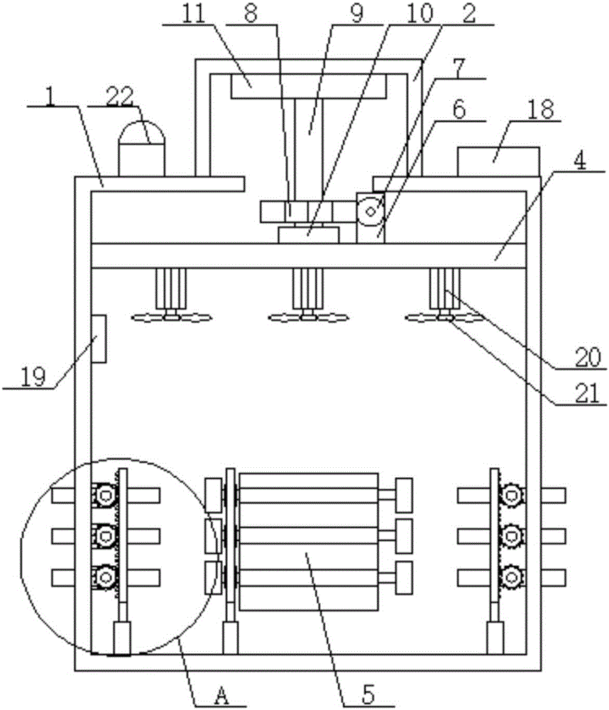
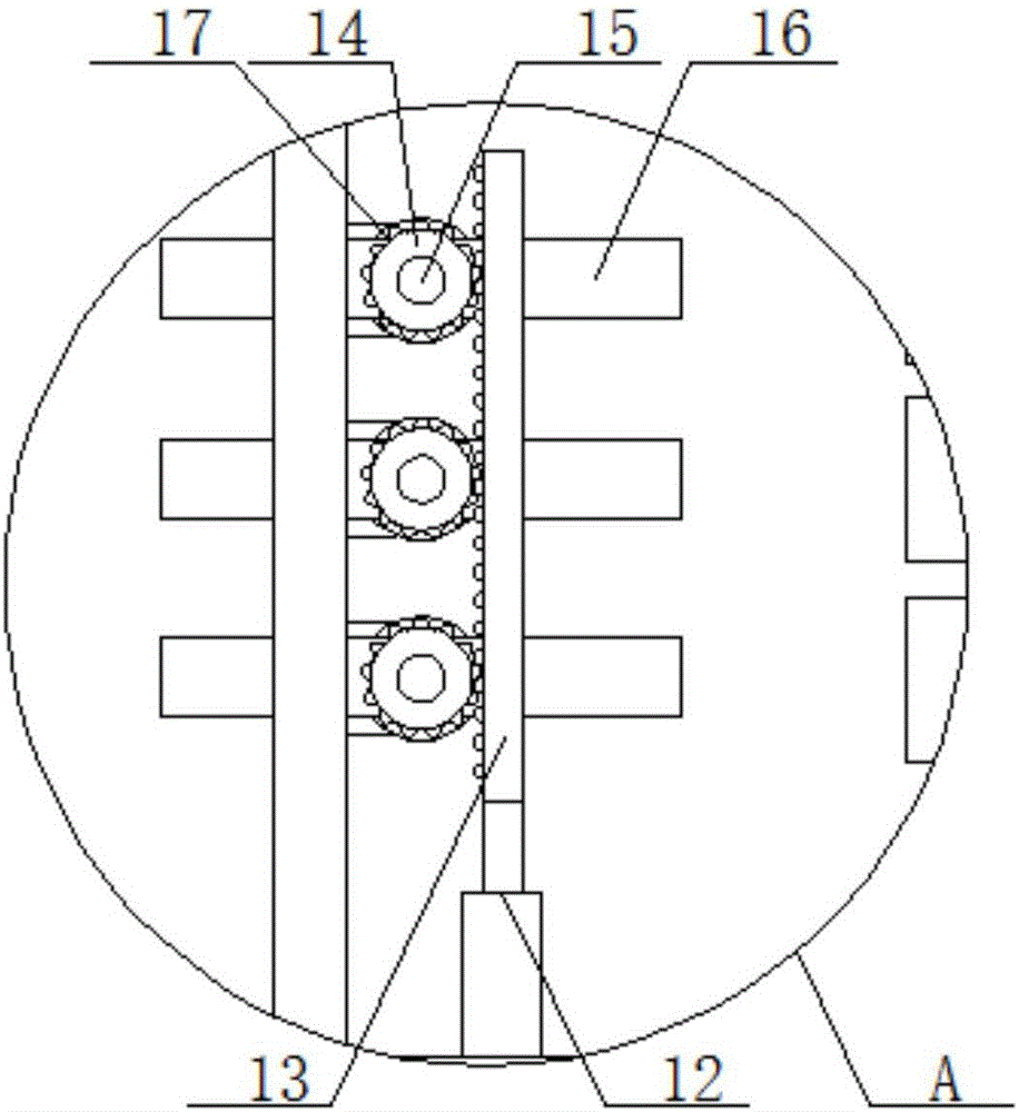
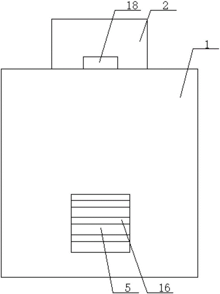
[0021] The present invention will now be described in further detail with reference to the drawings. These drawings are all simplified schematic diagrams, which merely illustrate the basic structure of the present invention in a schematic manner, so they only show the structures related to the present invention.

[0022] Such as Figure 1-5 As shown, a power distribution box with high heat dissipation performance and rainproof performance includes a main body 1, a heat dissipation chamber 2, a top heat dissipation mechanism, and a side heat dissipation mechanism. The heat dissipation chamber 2 is cylindrical, and the heat dissipation chamber 2 is vertical. The top surface of the heat dissipation chamber 2 is provided with first heat dissipation holes 3, and there are several first heat dissipation holes 3, and each first heat dissipation hole 3 is uniformly circumferentially arranged along the center of the top surface of the heat dissipation chamber 2. The heat dissipation cham...


PUM


Abstract

The invention relates to a distribution box with the high dissipation performance and rainproof performance. The distribution box comprises a body, a heat dissipation chamber, a top face heat dissipation mechanism and a side face heat dissipation mechanism. The top face heat dissipation mechanism comprises a first motor, a worm, a worm wheel, a first rotating shaft, a first bearing and a baffle. The side face heat dissipation mechanism comprises an air cylinder, a rack and a side face heat dissipation unit. The side face heat dissipation unit comprises a plurality of side face heat dissipation assemblies. According to the distribution box with the high dissipation performance and rainproof performance, a top face heat dissipation hole and side face heat dissipation openings are formed, when it is fine, the heat dissipation hole is completely opened through the top face heat dissipation mechanism, and the heat dissipation openings are opened to the largest extent through the side face heat dissipation mechanism, so that heat is emitted out through the multiple large heat dissipation openings, and the high heat dissipation performance is achieved; when it rains, the top face heat dissipation hole is closed so as to prevent water leakage; meanwhile, an adjusting plate is rotated to a certain angle, the heat dissipation openings are opened to a small extent, raindrops are shielded while heat dissipation is performed, and the rainproof performance is achieved.

Description

Technical field [0001] The invention relates to the field of distribution boxes, in particular to a distribution box with high heat dissipation performance and rainproof performance. Background technique [0002] The distribution box is the assembly of switchgear, measuring instruments, protective appliances and auxiliary equipment in closed or semi-enclosed metal cabinets or screens according to electrical wiring requirements to form the cabinet of low-voltage power distribution devices. These equipment, meters and electrical appliances are A lot of heat will be generated during use, and some distribution boxes that operate outdoors will generate high temperatures under the sunlight, especially in the summer season, the temperature inside the box will greatly exceed the environmental temperature specified by these appliances, if If the heat is not released in time, these devices may be burned. The current common way of dissipating heat is to open heat dissipation holes on the bo...

Claims


Application Information

Patent Timeline
Patent Type & Authority Applications(China)
IPC IPC(8): H02B1/56H02B1/28
CPCH02B1/28H02B1/565
Inventor 陈鸣辉
Owner 黑龙江省一滴水环保科技有限公司
Why Eureka
Try Eureka