Dual-drive cable terminal fastening device

A cable termination and fastening device technology, applied in the direction of connecting/terminating cables, etc., can solve the problems of increased difficulty, randomness, and reduced cable insulation, so as to save operation difficulty, save operation space, and facilitate operation. Effect

Inactive Publication Date: 2017-05-31
GUANGZHOU PANYU CABLE WORKS
View PDF8 Cites 14 Cited by
  • Summary
  • Abstract
  • Description
  • Claims
  • Application Information

AI Technical Summary

Problems solved by technology

[0002] It is very important to ensure the safe and stable operation of the power grid in today's society. The cable is erected on the pole or building through the street yard. The fixing of the cable end is generally to bend the cable end around the street yard and then bend it Under tension, bind or fix the bent cable ends; at present, construction workers usually use traditional methods such as manpower or simple tools to bend the cable ends and use binding wires to bind and fix the bent cable ends. Because the diameter of the cable is relatively thick, it is difficult for personnel working at heights to bend and tighten the cable only by manpower or simple tools, and the cable itself is very elastic when it is bent, and it is easy to bounce or slip off from the hands or simple tools. Increased the difficulty of construction
The binding wires are generally thin aluminum metal wires. Tightening the cables will reduce the insulation of the cables and easily cause damage to the outer layer of the cable insulation. Moreover, there is no uniform standard for the binding method, which is very random, resulting in the firm binding of the cable ends. It is difficult to guarantee the safety, and the cable end is easy to loosen and fall off from the street yard, which brings safety hazards

Method used


Image

  • Dual-drive cable terminal fastening device
  • Dual-drive cable terminal fastening device
  • Dual-drive cable terminal fastening device

Examples


Embodiment Construction

[0029] A double-drive type cable terminal fastening device of the present invention will be further described below in conjunction with the accompanying drawings:

[0030] It should be noted that the terms "upper", "lower", "front", "rear" and similar expressions used in this specification are only for the purpose of illustration, and are determined according to the actual situation in the embodiment.

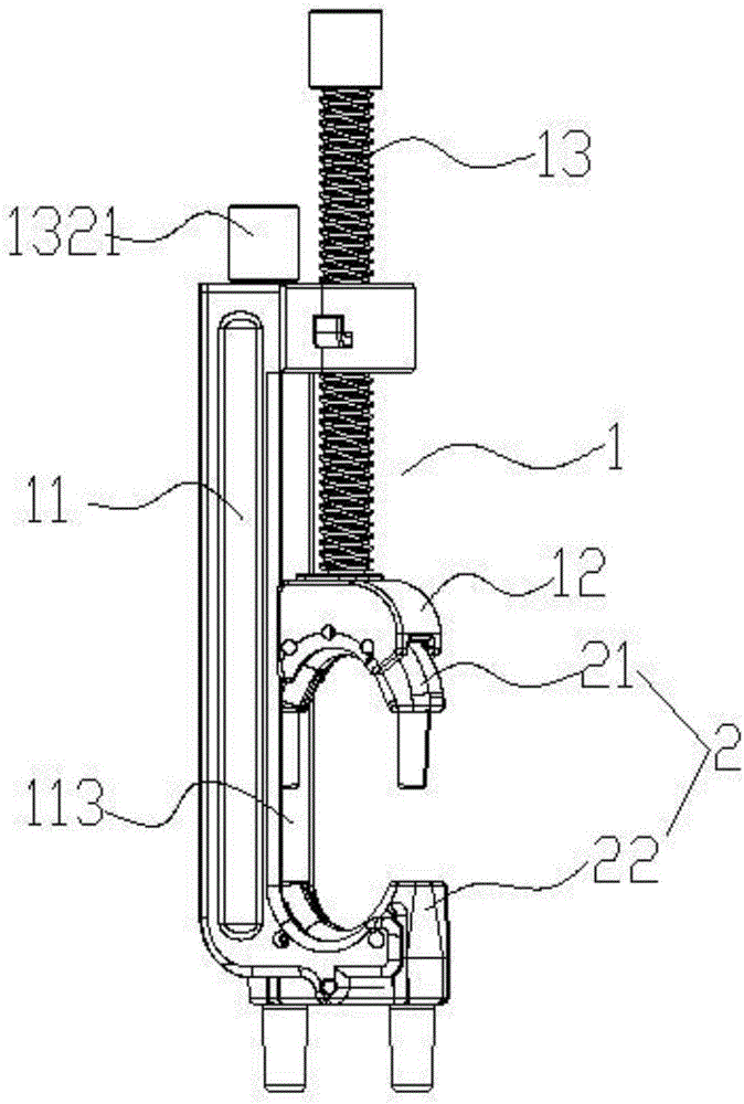
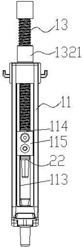
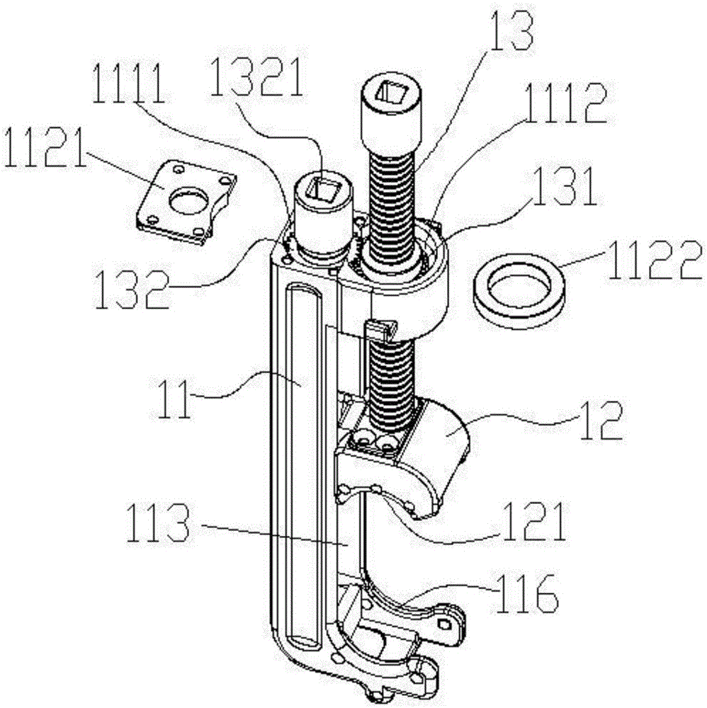
[0031] Such as Figure 1-5As shown, a double-drive type cable terminal fastening device includes a cable terminal fastening device 1 and a fastening clamp 2. The cable terminal fastening device 1 includes a crimping body 11, a dynamic pressure block 12 and a pressing mechanism. The top and the bottom of the wire body 11 are arranged oppositely, and the dynamic pressure block 12 is located between the top and the bottom of the wire body 11 and is opposite to the bottom. The rotatably connected compression screw 13, the driven gear 131 that drives the compression screw 13 to rec...


PUM


Abstract

The invention discloses a dual-drive cable terminal fastening device. The device comprises a line ball body, a dynamic pressure block, a compression screw rod, a driven gear and a driving gear. The driven gear and the driving gear are movably installed in the top of the line ball body and rotate freely. The inner surface of the driven gear is connected with a fastening screw rod in a threaded connection way. The outer surface of the driven gear is intermeshed with the outer surface of the driving gear. The reciprocating motion of the compression screw rod relative to the bottom of the line ball body is adjusted by rotating the driving gear. A fastening cable clamp comprises a U-shaped male clamp and a female clamp. The back of U-shaped male clamp is tightly matched with the lower surface of the dynamic pressure block. The back of the female clamp is tightly matched with the bottom of the line ball body. The matched non-return self-locking mechanism is disposed in the U-shaped male clamp and female clamp, and can be rapidly matched and locked to enable the U-shaped male clamp and female clamp to tightly clamp a cable. The fastening device with two modes of operation is labor-saving, can compress cables round street codes and porcelain insulators together rapidly, and fasten fixedly the bended ends of cables by the fastening cable clamp installed on the device.

Description

technical field [0001] The invention relates to the field of power tools, in particular to a double-drive type cable terminal fastening device. Background technique [0002] It is very important to ensure the safe and stable operation of the power grid in today's society. The cable is erected on the pole or building through the street yard. The fixing of the cable end is generally to bend the cable end around the street yard and then bend it Under tension, bind or fix the bent cable ends; at present, construction workers usually use traditional methods such as manpower or simple tools to bend the cable ends and use binding wires to bind and fix the bent cable ends. Because the diameter of the cable is relatively thick, it is difficult for personnel working at heights to bend and tighten the cable only by manpower or simple tools, and the cable itself is very elastic when it is bent, and it is easy to bounce or slip off from the hands or simple tools. Increased the difficult...

Claims


Application Information

Patent Timeline
Patent Type & Authority Applications(China)
IPC IPC(8): H02G1/14
CPCH02G1/14
Inventor 胡超强尤占山孙建吉覃丹陈雪儿卢广业张开拓王延发张仕欢郝燕邵源鹏程雪丽
Owner GUANGZHOU PANYU CABLE WORKS
Why Eureka
Try Eureka