Droop Control Method for DC Microgrid

A control method and DC micro-grid technology, applied in the direction of DC network circuit devices, electrical components, circuit devices, etc., can solve the problems of power distribution accuracy reduction, DC bus voltage deviation, etc., and achieve the effect of improving the system voltage quality

Inactive Publication Date: 2019-10-11
STATE GRID ZHEJIANG XINCHANG POWER SUPPLY +3
View PDF2 Cites 0 Cited by
  • Summary
  • Abstract
  • Description
  • Claims
  • Application Information

AI Technical Summary

Problems solved by technology

[0004] Although droop control has many advantages, in low voltage DC systems, the influence of wiring resistance cannot be ignored
Therefore, when using conventional droop control, there are two problems that cannot be solved at the same time
First: the output voltage of the micro-source will decrease linearly with the increase of the output current. When the output current of the micro-source is very large or a large droop coefficient is selected, the DC bus will produce a large voltage deviation; second, due to the micro-source There is a connection resistance between the source and the DC bus, and the accuracy of power distribution will be greatly reduced

Method used


Image

  • Droop Control Method for DC Microgrid
  • Droop Control Method for DC Microgrid
  • Droop Control Method for DC Microgrid

Examples


Embodiment Construction

[0040] The technical solution of the present invention will be further described in detail below in conjunction with the accompanying drawings.

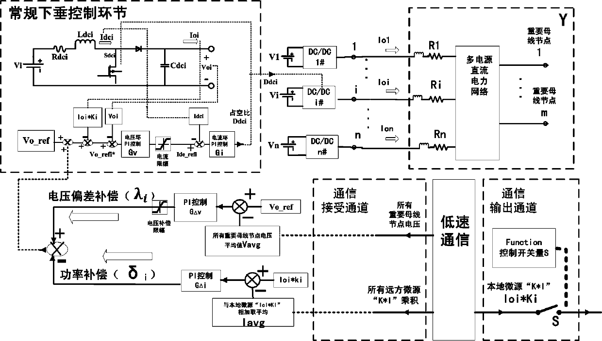
[0041] The present invention proposes an improved droop control scheme based on the average current between micro-sources and important bus voltage as feedback signals. This method can ideally realize the current / power of each micro-source and its droop coefficient K i Allocation in inverse proportion; the introduced voltage of important busbars (the microgrid operator determines which nodes are important busbars and installs corresponding communication channels) can better improve the voltage quality of the system; at the same time, the designed full-load micro-source chain stop power signal The scheme can ensure that when the micro-sources select an unreasonable droop coefficient, even if one micro-source is fully loaded, other micro-sources that are not fully loaded can still not be clamped by the fully-loaded micro-sources, and co...


PUM


Abstract

The invention discloses a direct-current microgrid droop control method and relates to droop control methods, for solving the problem existing in conventional droop control that micro-source output voltage is decreased linearly along with increase of output current, direct-current bus generates high voltage deviation, and power distribution precision is low. The direct-current microgrid droop control method includes the steps of 1, introducing information of all micro-source output current and important bus voltage through low-speed communication; 2, implementing a linkage mechanism of current limit and current signal sending pause, to be specific, detecting power sent by every micro-source, sending an instruction to cut off a communication output channel switch once detecting that some of the micro-sources is loaded fully to prevent the micro-source from sending its current signal outwards but to allow the same to receive current signal sent from the other micro-sources and continue to generate power compensation and voltage compensation; and sending an instruction to close the communication output channel switch once detecting that the micro-source is not in full load. The direct-current microgrid droop control method improves quality of system voltage and guarantees normal running of the microgrid system even when the micro-sources select unreasonable droop coefficient.

Description

technical field [0001] The invention relates to a droop control method, in particular to a droop control method of a DC microgrid. Background technique [0002] In recent years, with the rapid development of distributed power supply and the continuous maturity of power electronic technology, the composition of power supply and load in the power grid has changed significantly. Therefore, more and more researchers pay attention to the DC microgrid. [0003] The important goal of coordinated control in the DC microgrid system is to achieve a reasonable load distribution among distributed power sources. Currently, there are two types of load distribution methods: centralized and distributed. The latter is more redundant and economical, easy to plug and play. The most widely used distributed load distribution method for microgrids is droop control. [0004] Despite the many advantages of droop control, the influence of wiring resistance cannot be ignored in low-voltage DC sys...

Claims


Application Information

Patent Timeline
Patent Type & Authority Patents(China)
IPC IPC(8): H02J1/00
Inventor 张文青王春雷陈奇方邹凯张学恒冯浩然庞惠飞董伟英章丽江甄少屿
Owner STATE GRID ZHEJIANG XINCHANG POWER SUPPLY
Why Eureka
Try Eureka