
Device and method for regulating reactive power of a wind turbine

A wind turbine and power technology, applied in wind power generation, reactive power adjustment/elimination/compensation, circuit devices, etc., can solve the adjustment error of wind turbine reactive power, slow response speed of fan reactive power, reactive The power is difficult to accurately estimate and other problems, to achieve the effect of low response speed, no hardware parameters, and increased cost

Active Publication Date: 2019-03-12
BEIJING GOLDWIND SCI & CREATION WINDPOWER EQUIP CO LTD
View PDF5 Cites 0 Cited by
  • Summary
  • Abstract
  • Description
  • Claims
  • Application Information

AI Technical Summary

Problems solved by technology

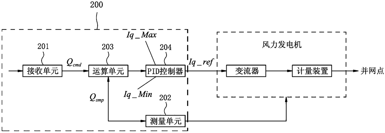
However, according to the prior art device 200 for regulating the reactive power of a wind turbine, no matter from which measuring point the measuring unit 202 measures, there is a drawback
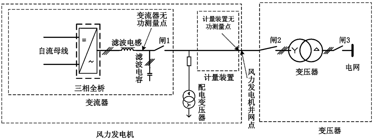
[0009] In the case where the measurement unit 202 of the device 200 measures the reactive power of the wind turbine from the reactive power measurement point of the converter, since the reactive power measurement point of the converter is not the grid connection point of the wind turbine, there are filter capacitors and There are differences in distribution transformers and hardware. It is difficult to accurately estimate the reactive power of this part, and there will be errors in the calculated reactive power. Therefore, there are errors in the adjustment of reactive power of wind turbines.
[0010] In the case where the measurement unit 202 of the device 200 measures the reactive power of the wind turbine from the reactive power measurement point of the metering device, the response speed of the wind turbine reactive power regulation is slow due to the generally slow response speed of the metering device

Method used


Image

  • Device and method for regulating reactive power of a wind turbine
  • Device and method for regulating reactive power of a wind turbine
  • Device and method for regulating reactive power of a wind turbine

Examples


Embodiment Construction

[0041] The following description with reference to the accompanying drawings is provided to assist in a comprehensive understanding of embodiments of the present invention as defined by the claims and their equivalents. Various specific details are included to aid in understanding but are to be regarded as exemplary only. Accordingly, those of ordinary skill in the art will recognize that various changes and modifications of the embodiments described herein can be made without departing from the scope and spirit of the invention. Also, descriptions of well-known functions and constructions are omitted for clarity and conciseness.

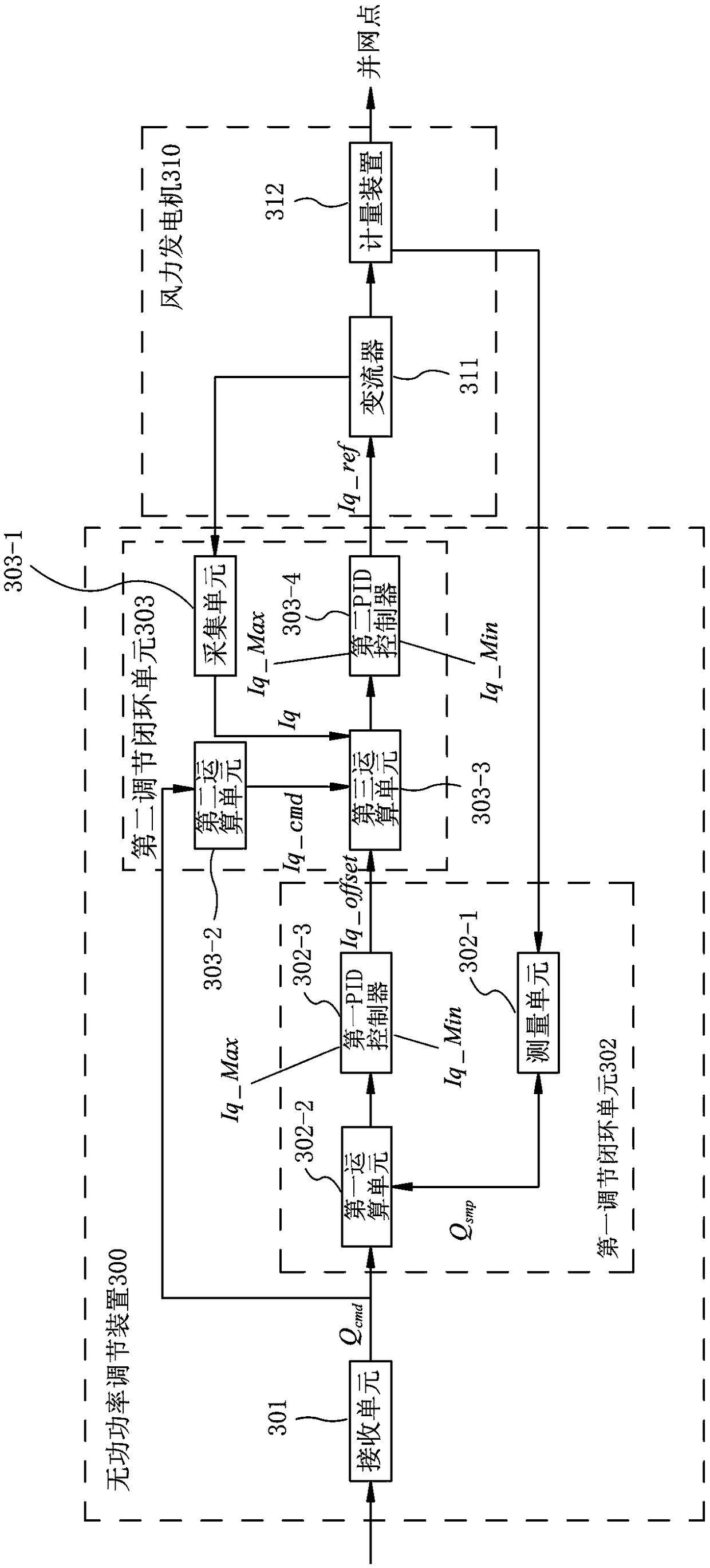
[0042] The invention proposes a device and a method for adjusting the reactive power of a wind power generator by adopting a double-closed-loop reactive power regulation method. Here, the double closed loop refers to a reactive current regulation closed loop and a reactive current deviation calibration closed loop. The reactive current deviation c...


PUM


Abstract

The invention provides equipment and method for adjusting reactive power of a wind driven generator. The equipment comprises a receiving element, a first adjusting closed-loop unit and a second adjusting closed-loop unit. The receiving element receives needed reactive power of the wind driven generator; the first adjusting closed-loop unit computes and outputs gauged reactive current for calibrating the deviation of reactive power, based on the received needed reactive power and the reactive power of the wind driven generator measured by a metering mechanism of the wind driven generator; the second adjusting closed-loop unit, based on the received reactive power, outputted gauged reactive current and the reactive current collected from a converter of the wind driven generator, computes reference reactive current for adjusting the reactive current of the converter and outputs the computed reference reactive current to the converter of the wind driven generator for adjusting the reactive current collected from the converter of the wind driven generator. The device and the method are capable of adjusting the reactive power of the wind driven generator quickly and accurately.

Description

technical field [0001] The present invention relates to the technical field of wind power, and more specifically relates to a device and method for adjusting reactive power of a wind power generator by adopting a double-closed-loop reactive power adjustment method. Background technique [0002] In recent years, with the development of new energy development projects, the wind power industry has been vigorously developed. A wind turbine is an electrical device that converts wind energy into mechanical energy and then converts mechanical energy into electrical energy. Wind power is becoming an increasingly popular and supported way of generating electricity because it has no fuel issues, nor does it produce radiation or air pollution. [0003] In terms of wind power generation technology, the power grid requires wind power plants to have reactive power adjustment devices. Using wind turbines to provide reactive power can reduce the wind field’s investment in reactive power ad...

Claims


Application Information

Patent Timeline
Patent Type & Authority Patents(China)
IPC IPC(8): H02J3/38H02J3/18
CPCH02J3/1885H02J3/386Y02E10/76Y02E40/30
Inventor 武磊杨志千
Owner BEIJING GOLDWIND SCI & CREATION WINDPOWER EQUIP CO LTD
Learn More