Charge-discharge circuit, mobile terminal and battery charge-discharge control method

A charging and discharging circuit and discharging circuit technology, applied in the field of electronics, can solve the problems of single charging and discharging method of batteries and low compatibility of chargers, etc.

Inactive Publication Date: 2017-05-31
VIVO MOBILE COMM CO LTD +1
View PDF5 Cites 16 Cited by
  • Summary
  • Abstract
  • Description
  • Claims
  • Application Information

AI Technical Summary

Problems solved by technology

[0004] Embodiments of the present invention provide a charging and discharging circuit, a mobile terminal, and a battery charging and discharging control method to solve the problems caused by the single charging and discharging method of the existing mobile terminal and the low compatibility with the charger. defect problem

Method used


Image

  • Charge-discharge circuit, mobile terminal and battery charge-discharge control method
  • Charge-discharge circuit, mobile terminal and battery charge-discharge control method
  • Charge-discharge circuit, mobile terminal and battery charge-discharge control method

Examples


no. 1 example

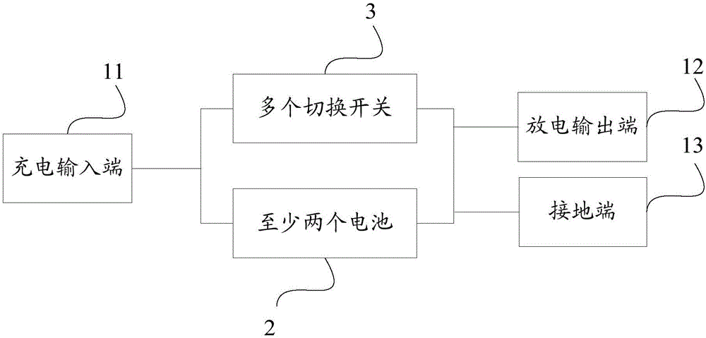
[0024] refer to figure 1 As shown, the charging and discharging circuit of the embodiment of the present invention includes:

[0025] Charging input terminal 11, discharging output terminal 12 and grounding terminal 13;

[0026] At least two batteries 2 are respectively connected to the charging input terminal 11, the discharging output terminal 12 and the ground terminal 13;

[0027] A plurality of switches 3, respectively including on-off and off-states, connected to the connection circuit where the at least two batteries 2 are connected to the charging input end 11, the discharge output end 12 and the ground end 13 ;

[0028] By controlling the connection or disconnection of a plurality of switches 3, the charging and discharging circuit is formed as a series charging circuit, a parallel charging circuit, a separate charging circuit, a series discharging circuit, a parallel discharging circuit or a separate discharging circuit.

[0029] Specifically, by controlling the c...

no. 2 example

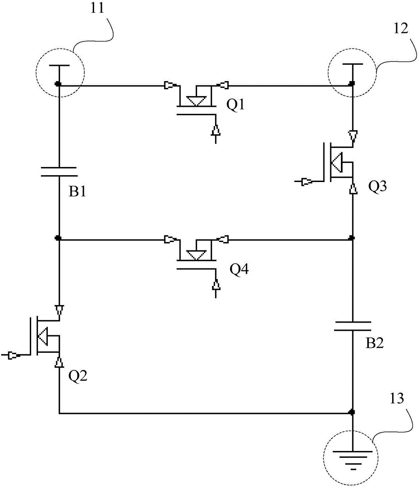
[0033] The embodiment of the present invention is a charging and discharging circuit for two batteries.

[0034] refer to figure 1 , 2 As shown, the charging and discharging circuit of the embodiment of the present invention includes:

[0035] Charging input terminal 11, discharging output terminal 12 and grounding terminal 13;

[0036] At least two batteries 2 are respectively connected to the charging input terminal 11, the discharging output terminal 12 and the ground terminal 13;

[0037] A plurality of switches 3, respectively including on-off and off-states, connected to the connection circuit where the at least two batteries 2 are connected to the charging input end 11, the discharge output end 12 and the ground end 13 ;

[0038] By controlling the connection or disconnection of a plurality of switches 3, the charging and discharging circuit is formed as a series charging circuit in which at least two batteries 2 are connected in series between the charging input te...

no. 3 example

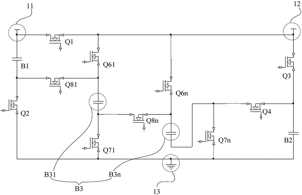
[0058] The embodiment of the present invention is a charging and discharging circuit for three or more batteries.

[0059] refer to figure 1 , 3 , 4, the charging and discharging circuit of the embodiment of the present invention includes:

[0060] Charging input terminal 11, discharging output terminal 12 and grounding terminal 13;

[0061] At least two batteries 2 are respectively connected to the charging input terminal 11, the discharging output terminal 12 and the ground terminal 13;

[0062] A plurality of switches 3, respectively including on-off and off-states, connected to the connection circuit where the at least two batteries 2 are connected to the charging input end 11, the discharge output end 12 and the ground end 13 ;

[0063] By controlling the connection or disconnection of a plurality of switches 3, the charging and discharging circuit is formed as a series charging circuit in which at least two batteries 2 are connected in series between the charging inp...


PUM


Abstract

The invention provides a charge-discharge circuit, a mobile terminal and a battery charge-discharge control method, relates to the technical field of electronics and solves the problem of singleness of the existing battery charge-discharge mode. The charge-discharge circuit comprises a charge input terminal, a discharge output terminal, a grounding terminal, at least two batteries and multiple switches, wherein the multiple switches are connected to a connecting circuit of the at least two batteries, the charge input terminal, the discharge output terminal and the grounding terminal; the charge-discharge circuit forms a series-connection charge circuit, a parallel-connection charge circuit, an independent charge circuit, a series-connection discharge circuit, a parallel-connection discharge circuit or an independent discharge circuit by controlling connection or disconnection of the multiple switches. According to the scheme, the charge-discharge mode is enriched, compatibility with a charger is improved, the problems such as high charge heat, high discharge loss, high requirements for interfaces and channels and the like of a single charge-discharge mode can be solved, and charge-discharge experience is improved.

Description

technical field [0001] The present invention relates to the field of electronic technology, and more specifically, to a charging and discharging circuit, a mobile terminal and a method for controlling battery charging and discharging. Background technique [0002] Existing mobile terminals can only use one of battery charging and discharging in parallel or in series. If the batteries are connected in parallel, the current will be larger during charging, and the heating caused by the path impedance will be more serious, and the requirements for the interface and the path will be higher. If the batteries are connected in series, the voltage needs to be discharged to the system through the step-down link during discharge, and the step-down link has a large loss, which affects the development of the charging industry. [0003] Therefore, the battery charging and discharging method of the existing mobile terminal is single, and the compatibility with the charger is low, and defe...

Claims


Application Information

Patent Timeline
Patent Type & Authority Applications(China)
IPC IPC(8): H02J7/00
CPCH02J7/0024
Inventor 李达寰张晓洪
Owner VIVO MOBILE COMM CO LTD
Why Eureka
Try Eureka