A Dynamic Compensation Circuit Applicable to Current Mode PWM Controller
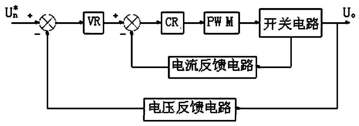
A technology of dynamic compensation and controller, applied in the direction of electrical components, output power conversion devices, etc., can solve the problems of large loss in the compensation mode of the current-type PWM control circuit, etc., and achieve fast response of over-current protection, sensitive over-current protection function, The effect of reducing loss
- Summary
- Abstract
- Description
- Claims
- Application Information
AI Technical Summary
Problems solved by technology
Method used
Image
Examples
Embodiment Construction
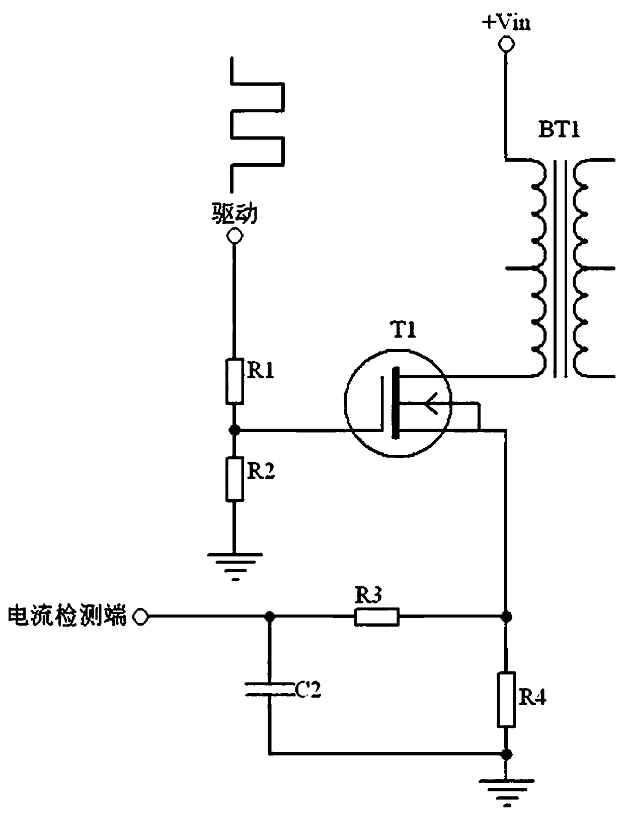
[0013] Such as Figure 6 shown, according to Figure 6 The circuit diagram given in , describes the circuit connection relationship between the following components, including the drive pin of the PWM control circuit and the current detection terminal of the PWM control circuit. The drive pin of the PWM control circuit is connected to one end of the resistor R1 and resistor R5 respectively. The other end of the resistor R1 is connected to one end of the resistor R2 and the gate of the switch tube T1, and the other end of the resistor R2 is grounded; the drain of the switch tube T1 is connected to one end of the primary winding of the transformer BT1, and the primary winding of the transformer BT1 The other end is connected to the input terminal +Vin; the source of the switch tube T1 is respectively connected to one end of the resistor R4, one end of the resistor R3, and the cathode of the diode D1; the anode of the diode D1 is connected to the other end of the resistor R5, and...
PUM
 Abstract
Description
Claims
Application Information
 - R&D
- Intellectual Property
- Life Sciences
- Materials
- Tech Scout
- Unparalleled Data Quality
- Higher Quality Content
- 60% Fewer Hallucinations
Browse by: Latest US Patents, China's latest patents, Technical Efficacy Thesaurus, Application Domain, Technology Topic, Popular Technical Reports.
© 2025 PatSnap. All rights reserved.Legal|Privacy policy|Modern Slavery Act Transparency Statement|Sitemap|About US| Contact US: help@patsnap.com


