Power allocation method based on reducing upper bound of real error bit probability

A technology of error bits and allocation methods, applied in radio transmission systems, advanced technologies, electrical components, etc., can solve the problems of high computational complexity, poor bit error rate performance, etc. and the effect of high BER performance

Active Publication Date: 2017-05-31
UNIV OF ELECTRONICS SCI & TECH OF CHINA
View PDF4 Cites 3 Cited by
  • Summary
  • Abstract
  • Description
  • Claims
  • Application Information

AI Technical Summary

Problems solved by technology

The present invention aims at the problem that the bit error rate performance of the PSM-MIMO system is poor when the channel condition is poor, and proposes an optimal adaptive power allocation algorithm based on convex optimization; for the calc...

Method used


Image

  • Power allocation method based on reducing upper bound of real error bit probability
  • Power allocation method based on reducing upper bound of real error bit probability
  • Power allocation method based on reducing upper bound of real error bit probability

Examples


Embodiment Construction

[0031] The technical solution of the present invention will be described in detail below in combination with the embodiments and the accompanying drawings.

[0032] In order to describe the present invention better, the terms used in the technical solution of the present invention and the MIMO system receiver structure are firstly introduced.

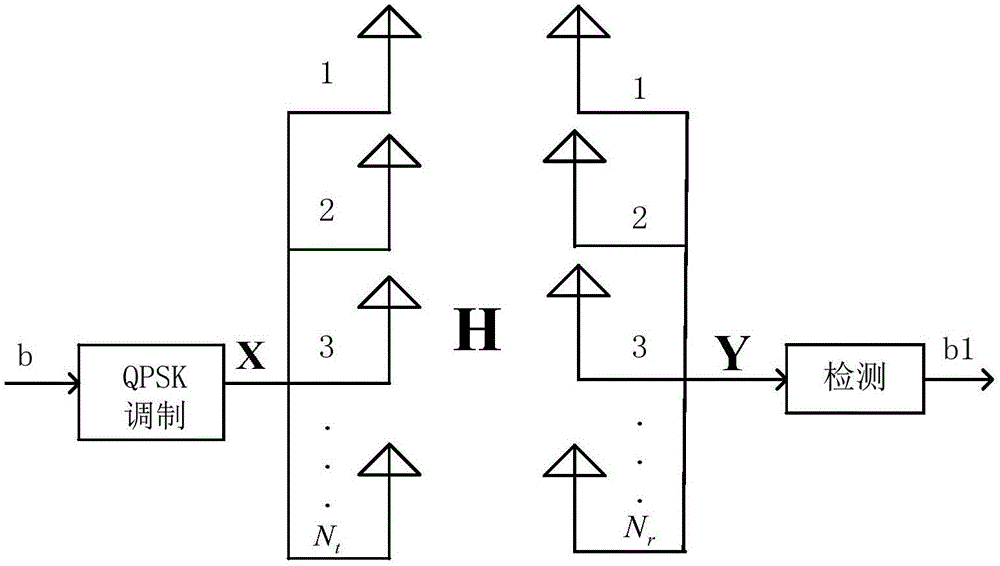
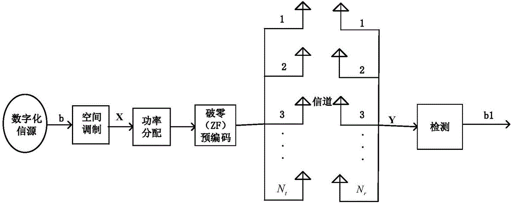
[0033] MIMO system: such as figure 1 , b is the bit data to be transmitted, which can be regarded as an L×T matrix, where L=log2(4) is the number of bits carried by a QPSK symbol. figure 2 , gave an N t root transmit antenna and N r An example of power allocation using the present invention for root receiving antennas.

[0034] Specific embodiments of the present invention are as figure 2 The system diagram shown.

[0035] B. Calculation process of two power allocation matrices

[0036] B1. Calculate the optimal power allocation matrix based on convex optimization

[0037] In the present invention, the traditional modulation co...


PUM


Abstract

The invention belongs to the technical field of communication anti-jamming, and especially relates to an MIMO (Multiple Input Multiple Output) technology, a PSM (Precoding Aided Spatial Modulation) technology and a power allocation technology. The invention provides a power allocation method based on reducing an upper bound of the real error bit probability. The invention proposes an optimal adaptive power allocation algorithm based on convex optimization in view of the relatively poor bit error rate performance of a PSM-MIMO system when the channel condition is bad; and proposes a power allocation algorithm with low complexity and approaching the bit error rate performance of the optimal power allocation algorithm aiming at the problem that the first power allocation algorithm based on the convex optimization is higher in computational complexity.

Description

technical field [0001] The invention belongs to the technical field of communication anti-jamming, and in particular relates to MIMO (Multiple Input Multiple Output) technology, PSM (Precoding Aided Spatial Modulation) technology and power distribution technology. Background technique [0002] MIMO technology is a high-speed transmission technology in a wireless environment. It configures multi-antenna units at the transmitter and receiver, and combines advanced space-time coding and modulation schemes. By making full use of the space degree of freedom, it can bring additional diversity. , multiplexing and beamforming gains. [0003] The PSM technology is a new technology in the MIMO system, which uses the index of the receiving antenna to carry information bits, and can further improve the performance of the MIMO system. However, due to the complex and changeable wireless channels, the channel conditions are not ideal in many cases, resulting in the deterioration of the sy...

Claims


Application Information

Patent Timeline
IPC IPC(8): H04B7/0413H04B7/0426
CPCH04B7/0413H04B7/0426Y02D30/70
Inventor 李尤雷霞肖悦喻凤蒋兆翔
Owner UNIV OF ELECTRONICS SCI & TECH OF CHINA
Why Eureka
Try Eureka