GPS synchronization method of distributed testing system

A test system and distributed technology, applied in the direction of time division multiplexing system, electrical components, multiplexing communication, etc., can solve the problems of poor anti-interference and difficult implementation, so as to reduce usage, improve synchronization efficiency, and avoid Effects of out-of-sync issues

Inactive Publication Date: 2017-05-31
ZHONGBEI UNIV
View PDF6 Cites 16 Cited by
  • Summary
  • Abstract
  • Description
  • Claims
  • Application Information

AI Technical Summary

Problems solved by technology

[0004] The purpose of the present invention is to solve the technical problems that the synchronization method of the existing distributed test system is difficult to implement in large-scale projects and has poor anti-interference performance, and to provide a synchronization method for the distributed test system based on GPS synchronization technology

Method used


Image

  • GPS synchronization method of distributed testing system
  • GPS synchronization method of distributed testing system
  • GPS synchronization method of distributed testing system

Examples


Embodiment Construction

[0028] The invention will be described in further detail below in conjunction with the accompanying drawings.

[0029] The GPS synchronization method of a kind of distributed testing system provided by the present invention, specific implementation is as follows:

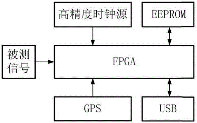
[0030] 1) Use the GPS timing module to generate and output two kinds of data, one is the PPS pulse signal, and the other is the UTC time t in the serial data corresponding to each PPS pulse signal. Such as figure 1 As shown, the PPS pulse generated by the GPS timing module and the on-site measured signal are input into the FPGA. The on-site measured signal is a digital signal output by the sensor and converted by subsequent conditioning and acquisition circuits. This part of the circuit does not belong to the synchronization unit. not shown in the figure;

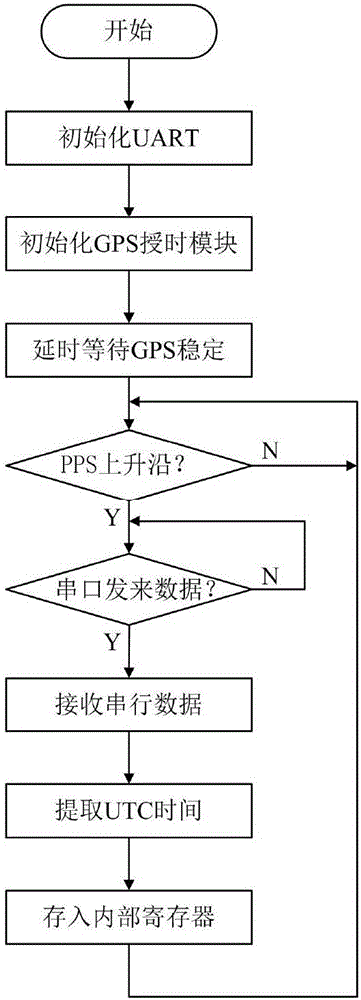
[0031] 2) Use FPGA to extract and cache the UTC time t generated by the GPS timing module. The specific operation steps are:

[0032] i. Integrate the UART se...


PUM


Abstract

The invention discloses a GPS synchronization method of a distributed testing system. The problem that the distributed testing systems are hard to be mutually synchronized since the independent working of each testing point causes the physical dispersion and isolation in the transient signal testing is solved by use of the method oriented to an application of the current mainstream distributed testing system. The method comprises the step of precisely measuring a time difference between a PPS pulse signal produced by a designed GPS synchronization unit and a received tested signal, wherein the time differences respectively measured by the testing points and the UTC time are upload to a computer so as to establish the time unification taking the PPS pulse as the standard on the computer. The GPS synchronization unit designed by the invention comprises a GPS timing module, a control chip FPGA and high-precision clock source, an EEPROM memory, and a USB interface. The GPS synchronization method disclosed by the invention is suitable for the synchronization of the distributed testing system under the outdoor open environment. The prominent problems of low reliability and high work amount in the wire synchronization are solved in a wireless synchronization method; the method is high in precision, simple in operation and easy for engineering realization.

Description

technical field [0001] The invention belongs to the technical field of synchronization methods for distributed test systems, and in particular relates to a GPS synchronization method for distributed test systems. This method is suitable for solving the synchronization problem of distributed measuring points in warhead damage test. Background technique [0002] Transient signals widely exist in the action of warheads, such as explosion pressure signals, shock vibration signals, etc., and their measurement has guiding significance for the development of weapon warheads. The transient signal is a single process with a short duration and a wide range of action, making it difficult to measure. Due to its high accuracy, reliability and applicability, the distributed test system has become the main transient signal test method at present. In practical applications, according to the scope of the transient signal, it is generally necessary to arrange several distributed measuring p...

Claims


Application Information

Patent Timeline
Patent Type & Authority Applications(China)
IPC IPC(8): H04J3/06
CPCH04J3/0638
Inventor 王代华宋林丽翟永王晓楠
Owner ZHONGBEI UNIV
Why Eureka
Try Eureka