Wireless communication method and device for reducing network delay

A wireless communication, low-latency technology, applied in the field of control channels for low-latency transmission

Active Publication Date: 2017-05-31
SHANGHAI LANGBO COMM TECH CO LTD
View PDF1 Cites 24 Cited by
  • Summary
  • Abstract
  • Description
  • Claims
  • Application Information

AI Technical Summary

Problems solved by technology

Another method is to map the uplink control channel to a short time s

Method used


Image

  • Wireless communication method and device for reducing network delay
  • Wireless communication method and device for reducing network delay
  • Wireless communication method and device for reducing network delay

Examples


Embodiment 1

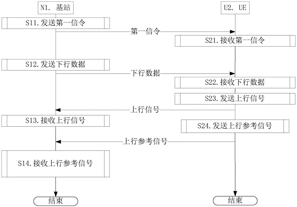
[0145] Embodiment 1 illustrates a flowchart of an embodiment of sending and receiving, as attached figure 1 Shown. Attached figure 1 Among them, the base station N1 is the maintenance base station of the serving cell of the UE U2.

[0146] For the base station N1, the first signaling is sent in step S11. The first signaling indicates a target subband set. The target subband set includes a positive integer number of subbands.

[0147] As an embodiment, the uplink signal is transmitted on a physical layer control channel. As a sub-embodiment of this embodiment, the physical layer control channel is PUCCH. As another sub-embodiment of this embodiment, the physical layer control channel is sTTI-PUCCH. Wherein, the sTTI-PUCCH is used to transmit uplink control information, and is located in a broadband symbol corresponding to a short time slot.

[0148] As an embodiment, the uplink signal is transmitted on a physical layer data channel. As a sub-embodiment of this embodiment, the ph...

Embodiment 2

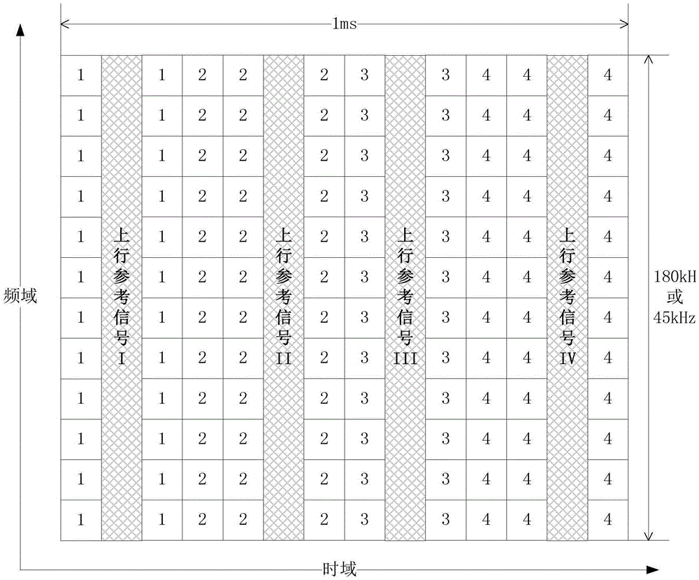
[0201] Embodiment 2 shows a schematic diagram showing the distribution of a short time slot in an LTE subframe according to the present invention. The LTE subframe includes 4 broadband symbols for uplink reference signal transmission, and the 4 broadband symbols for uplink reference signal transmission belong to four different short time slots. Fig. 2(a) and Fig. 2(b) are for N-CP (Normal-Cyclic Prefix) scenarios where SRS is not configured and SRS is configured. Figures 2(c) and 2(d) are for the case where SRS is not configured and SRS is configured in the E-CP (Extended-Cyclic Prefix) scenario. Such as Figure 2(a) to Figure 2(d) As shown, one LTE subframe includes 4 short time slots. The part marked "x" in the figure corresponds to the resource unit occupied by the uplink signal in the xth short time slot. The uplink signal and the uplink reference signal Y in the xth short time slot form the xth short time slot, and are composed of the same (One or more) antenna port (tha...

Embodiment 3

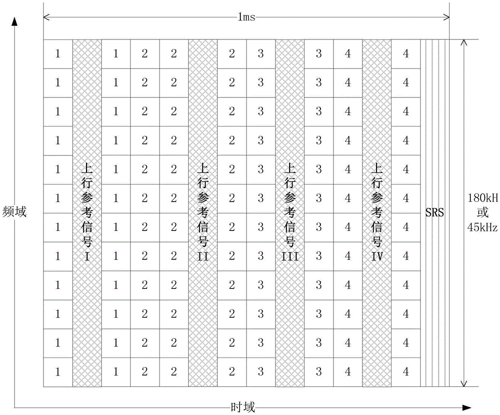
[0205] Embodiment 3 shows a schematic diagram of the distribution of a short time slot in an LTE subframe according to the present invention. The LTE subframe includes 4 broadband symbols for uplink reference signal transmission, and the 4 broadband symbols for uplink reference signal transmission can be shared by different short time slots. Figures 3(a) and 3(b) are for the case where SRS is not configured and SRS is configured in the N-CP scenario. Figures 3(c) and 3(d) are for the case where SRS is not configured and SRS is configured in the E-CP scenario. Such as Figure 3(a) to Figure 3(d) As shown, one LTE subframe includes 4 short time slots.

[0206] As a sub-embodiment, the part marked "x" in the figure corresponds to the resource unit occupied by the uplink signal in the xth short time slot, and the uplink signal and the uplink reference signal Y in the xth short time slot form the first short time slot. Time slot, and sent by the same antenna port (one or more) (that...


PUM


Abstract

The present invention discloses a wireless communication method and device for reducing network delay. The UE sends the upstream signal. The upstream signal occupies part or all of the broadband symbols of the first short time slot. The duration of the first short time slot is less than 1 millisecond; the first short time slot is located in the first LTE subframe in the time domain; the first LTE subframe includes N short time slots. The number of the broadband symbols in the first short time slot is related to the location of the first short time slot in the first LTE subframe. If the first short time slot is the last short time slot in the N short time slots and includes the last broadband symbol of the first LTE subframe, the number of broadband symbols in the first short time slot is no less than K. Through designing the distribution method of the new short time slots in the LTE subframe, and the mapping method of the corresponding upstream signal and upstream reference signal, the present invention ensures channel estimation and transmission performance of the upstream signal and avoids the conflict of signal and SRS in the short time slot.

Description

Technical field [0001] The present invention relates to a transmission scheme in a wireless communication system, in particular to a control channel method and device based on low-delay transmission of a cellular network. Background technique [0002] In the 3GPP (3rd Generation Partner Project) RAN (Radio Access Network, radio access network) #63 plenary meeting, the topic of reducing the delay of the LTE network was discussed. The delay of LTE network includes air interface delay, signal processing delay, transmission delay between nodes, etc. With the upgrading of the wireless access network and core network, the transmission delay is effectively reduced. With the application of new semiconductors with higher processing speeds, signal processing delays have been significantly reduced. [0003] In LTE (LTE-Long Term Evolution), TTI (Transmission Time Interval) or subframe or PRB (Physical Resource Block, physical resource block) pair (Pair) corresponds to one ms (milli-second, ...

Claims


Application Information

Patent Timeline
IPC IPC(8): H04L5/00H04W72/04
CPCH04L5/0053H04L5/0055H04W72/0446H04W72/21
Inventor 蒋琦
Owner SHANGHAI LANGBO COMM TECH CO LTD
Why Eureka
Try Eureka