Electronic tube display protection device for electronic component

A technology for electronic components and protection devices, which is applied to the field of electronic tube display protection devices for electronic components, can solve the problems of wasting raw materials, economic losses, increasing electronic tubes, etc., and achieves the effect of neat appearance and reduced sales volume.

Inactive Publication Date: 2017-06-06
南昌安润科技有限公司
View PDF8 Cites 11 Cited by
  • Summary
  • Abstract
  • Description
  • Claims
  • Application Information

AI Technical Summary

Problems solved by technology

[0006] In order to overcome the disadvantages that electronic tubes are often artificially damaged during the display process, a large number of electronic tubes cannot be used, raw materials are wasted, and certain economic losses are caused. The technical problem to be solved by the present invention is to provide a fully displayable The new type of electronic tube can let people fully understand the new type of electronic tube, increase the sales of the new type of electronic tube, protect the electronic components of the new type of electronic tube, and use the electronic tube display protection device

Method used


Image

  • Electronic tube display protection device for electronic component
  • Electronic tube display protection device for electronic component
  • Electronic tube display protection device for electronic component

Examples


Embodiment 1

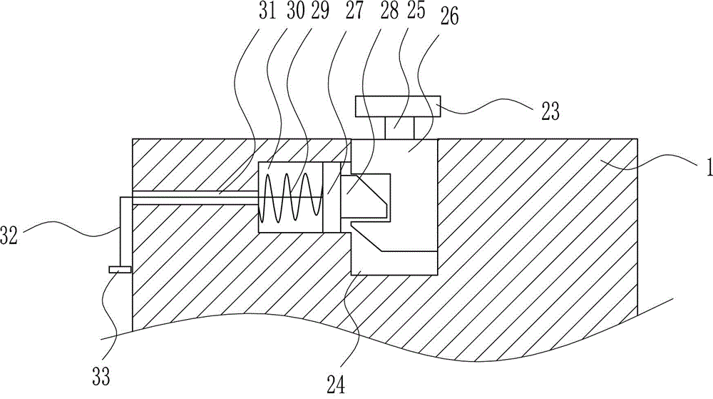
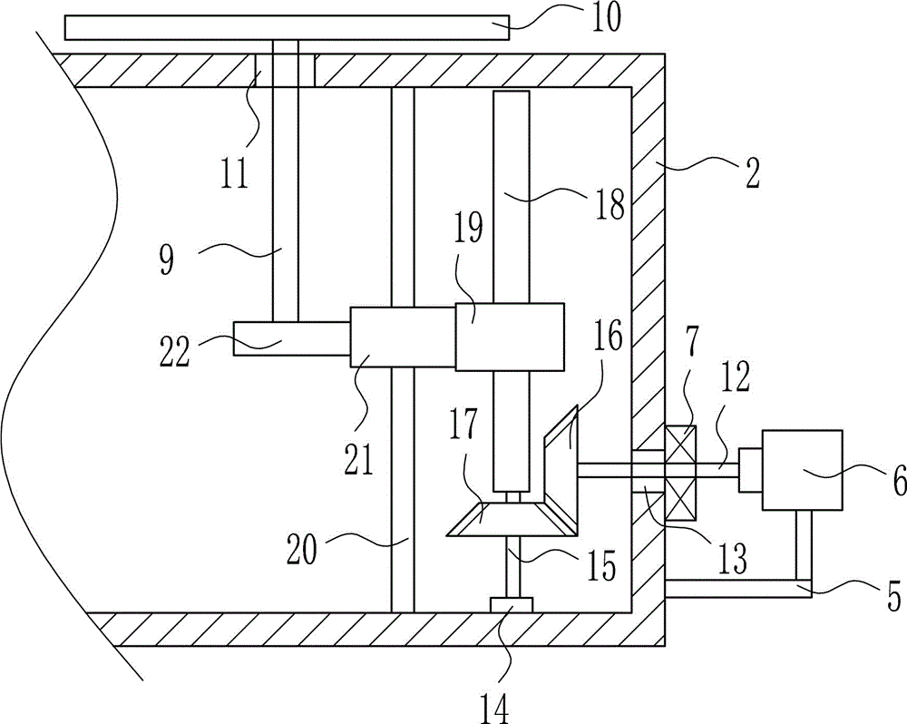
[0036] An electronic tube display protection device for electronic components, such as Figure 1-9 As shown, it includes a display table 1, a cabinet body 2, a partition 4, a bracket 5, a motor 6, a first bearing seat 7, a connecting rod 9, a placement plate 10, a first rotating shaft 12, a second bearing seat 14, a second Rotating shaft 15, first bevel gear 16, second bevel gear 17, screw rod 18, nut 19, slide bar 20, first slider 21 and fixed plate 22, the left side of display table 1 has through groove 3, through groove 3 The display table 1 in the middle is connected with a partition plate 4 by means of bolt connection, the right side of the display table 1 is connected with a cabinet body 2 by a method of bolt connection, and the lower part of the right side outside the cabinet body 2 is connected by a method of bolt connection. Bracket 5, the top of the bracket 5 is connected with the motor 6 by bolt connection, the right side outside the cabinet body 2 is connected with...

Embodiment 2

[0038] An electronic tube display protection device for electronic components, such as Figure 1-9 As shown, it includes a display table 1, a cabinet body 2, a partition 4, a bracket 5, a motor 6, a first bearing seat 7, a connecting rod 9, a placement plate 10, a first rotating shaft 12, a second bearing seat 14, a second Rotating shaft 15, first bevel gear 16, second bevel gear 17, screw rod 18, nut 19, slide bar 20, first slider 21 and fixed plate 22, the left side of display table 1 has through groove 3, through groove 3 The display table 1 in the middle is connected with a partition plate 4 by means of bolt connection, the right side of the display table 1 is connected with a cabinet body 2 by a method of bolt connection, and the lower part of the right side outside the cabinet body 2 is connected by a method of bolt connection. Bracket 5, the top of the bracket 5 is connected with the motor 6 by bolt connection, the right side outside the cabinet body 2 is connected with...

Embodiment 3

[0041] An electronic tube display protection device for electronic components, such as Figure 1-9 As shown, it includes a display table 1, a cabinet body 2, a partition 4, a bracket 5, a motor 6, a first bearing seat 7, a connecting rod 9, a placement plate 10, a first rotating shaft 12, a second bearing seat 14, a second Rotating shaft 15, first bevel gear 16, second bevel gear 17, screw rod 18, nut 19, slide bar 20, first slider 21 and fixed plate 22, the left side of display table 1 has through groove 3, through groove 3 The display table 1 in the middle is connected with a partition plate 4 by means of bolt connection, the right side of the display table 1 is connected with a cabinet body 2 by a method of bolt connection, and the lower part of the right side outside the cabinet body 2 is connected by a method of bolt connection. Bracket 5, the top of the bracket 5 is connected with the motor 6 by bolt connection, the right side outside the cabinet body 2 is connected with...


PUM


Abstract

The invention relates to an electronic component display protection device, in particular to an electronic tube display protection device for an electronic component, and aims to provide an electronic tube display protection device which can sufficiently display novel electronic tubes, enable people to sufficiently know the novel electronic tubes, increase the sales of the novel electronic tubes and protect the novel electronic tubes. The electronic tube display protection device for the electronic component comprises a display table, a cabinet, a partition, a support, a motor, a bearing block, a connecting rod, a placing plate, a first rotating shaft, a second bearing block, a second rotating shaft, a first bevel gear and the like, and a through groove is formed in the left side of the display table. According to the device, the placing plate rises and falls to adapt different heights of people to observe the novel electronic tubes, the electronic tubes are protected by the aid of glass covers, so that dust cannot adhere to the electronic tubes.

Description

technical field [0001] The invention relates to a display protection device for electronic components, in particular to an electronic tube display protection device for electronic components. Background technique [0002] Electronic components are components of electronic components and electric small machines and instruments. They are often composed of several parts and can be used in similar products; they often refer to certain parts in industries such as electrical appliances, radios, and instruments, such as capacitors and transistors. The general term for sub-devices such as springs, hairsprings, and springs. Common ones include diodes, etc. [0003] Electronic components include: resistors, capacitors, potentiometers, electron tubes, radiators, electromechanical components, connectors, semiconductor discrete devices, electroacoustic devices, laser devices, electronic display devices, optoelectronic devices, sensors, power supplies, switches, micro-motors , electroni...

Claims


Application Information

Patent Timeline
Patent Type & Authority Applications(China)
IPC IPC(8): A47F7/00A47F5/10
CPCA47F7/00A47F5/10
Inventor 不公告发明人
Owner 南昌安润科技有限公司
Why Eureka
Try Eureka