A jig for handling automobile leaf springs
A technology for moving cars and leaf springs, applied in the field of machinery, can solve the problems of easily damaged car leaf spring painting, leaf spring center of gravity deviation, heavy weight of automobile leaf springs, etc., to avoid local collision with the ground, simplify actual operation, and fix fixture structure simple effect
- Summary
- Abstract
- Description
- Claims
- Application Information
AI Technical Summary
Problems solved by technology
Method used
Image
Examples
Embodiment 1
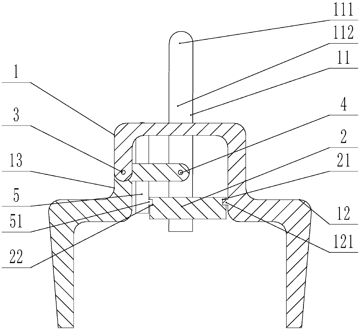
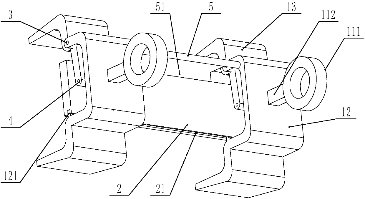
[0028] see figure 1 with figure 2 , in the present embodiment, the clamping structure 1 of the fixture of the present invention is arranged in two parallel to each other, the fixed rod 5 is in the shape of a "T", and the two ends of the horizontal part are respectively fixedly connected to two fixed claws 12 parallel to each other. , the magnet 2 is provided with a first groove 21 and a second groove 22, the first groove 21 is fixedly connected with the bump 121 on the fixed claw 12, the second groove 22 is fixedly arranged on the fixed claw 12 The block 51 on the fixed rod 5 is fixedly connected, and the first groove 21 and the second groove 22 are arranged on two parallel surfaces of the magnet 2 .
[0029] The length of the magnet 2 perpendicular to the clamping direction is greater than or equal to the length of the fixture in this direction, which increases the contact area between the magnet 2 and the automobile leaf spring, making the attraction stronger and making th...
Embodiment 2
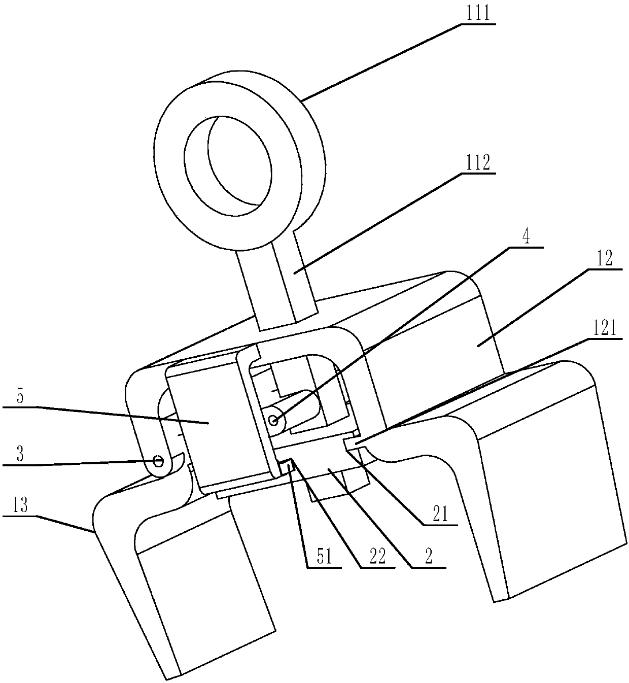
[0036] see figure 1 with image 3 ,
[0037] In this embodiment, the clamping structure 1 of the clamp of the present invention is provided as one, the fixed rod 5 is in the shape of "7", and the end away from the clamping block 51 is fixedly connected to the fixed claw 12, and the magnet 2 is provided with a first groove 21 And the second groove 22, the first groove 21 is fixedly connected with the protrusion 121 on the fixed claw 12, and the second groove 22 is fixedly connected with the block 51 fixedly arranged on the fixed rod 5 on the fixed claw 12 , the first groove 21 and the second groove 22 are arranged on two adjacent surfaces of the magnet 2 .
[0038] The fixture in this embodiment adopts a single jaw structure. Compared with the double jaw structure in Example 1, the structure is simpler and more versatile. When clamping the automobile leaf spring, it should be noted that the automobile plate should be clamped The center of the spring, try to ensure the stabil...
Embodiment 3
[0045] With reference to Example 1, in this embodiment, only the magnet 2 is respectively connected to the groove of the fixed claw 12 and the fixed rod 5, and the fixed clamping connection of the block is changed to use a locking screw to connect the magnet 2 to the fixed clamp respectively. Claw 12, fixed rod 5 locking fixed connection mode. This kind of fixed connection is more firm, and the stability of the fixture is higher.
PUM
 Abstract
Description
Claims
Application Information
 - R&D
- Intellectual Property
- Life Sciences
- Materials
- Tech Scout
- Unparalleled Data Quality
- Higher Quality Content
- 60% Fewer Hallucinations
Browse by: Latest US Patents, China's latest patents, Technical Efficacy Thesaurus, Application Domain, Technology Topic, Popular Technical Reports.
© 2025 PatSnap. All rights reserved.Legal|Privacy policy|Modern Slavery Act Transparency Statement|Sitemap|About US| Contact US: help@patsnap.com


