Clamp used for carrying automobile leaf spring

A technology for moving cars and leaf springs, which is applied in the field of machinery, can solve the problems of easily damaged car leaf spring painting, leaf spring center of gravity deviation, and car leaf spring damage, so as to avoid local collision with the ground, improve clamping efficiency, and simplify the actual situation. The effect of the operation

Active Publication Date: 2017-08-04
湖北远成鄂弓汽车悬架弹簧有限公司
View PDF7 Cites 0 Cited by
  • Summary
  • Abstract
  • Description
  • Claims
  • Application Information

AI Technical Summary

Problems solved by technology

The shape of the automobile leaf spring has the characteristics of flatness and small surface area per unit volume. The irregular shape makes it inconvenient for traditional clamping tools such as claws to tightly and firmly clamp the automobile leaf spring.
[0003] Existing automobile leaf springs are heavy in weight. Generally, when the claws clamp the automobile leaf spring, the automobile leaf spring will slip due to its heavy weight. If the claws with very large clamping force are used, during the clamping process The claws are easy to damage the paint of the automobile leaf spring, and even leave a gap on the automobile leaf spring, so that the automobile leaf spring is easy to be corroded, and also affects the appearance of the automobile leaf spring as a complete product, reducing the sales volume of the product. Therefore, the industry does not Claws are used to carry the automobile leaf spring, and magnets are often used to carry the automobile leaf spring, but the pure use of magnet suction to carry the automobile leaf spring will cause the magnet and the automobile leaf spring to slide relative to each other during the handling process, or even slip off, and the automobile leaf spring The change of the relative position with the magnet will cause the center of gravity of the leaf spring to shift, and it cannot be hoisted smoothly, and it will fall smoothly. When the car is put down, it will partially hit the ground and cause damage to the leaf spring of the car.

Method used


Image

  • Clamp used for carrying automobile leaf spring
  • Clamp used for carrying automobile leaf spring
  • Clamp used for carrying automobile leaf spring

Examples


Embodiment 1

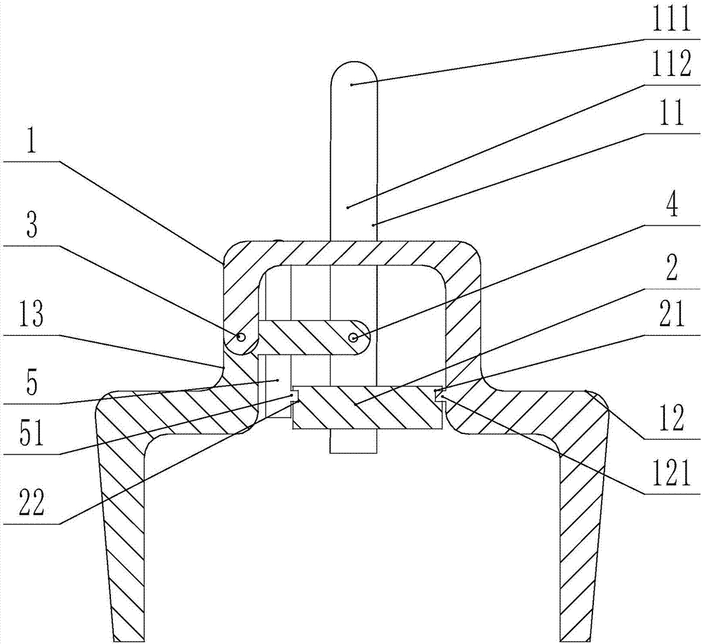
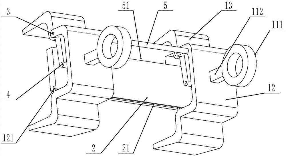
[0028] see figure 1 and figure 2 , in the present embodiment, the clamping structure 1 of the fixture of the present invention is arranged in two parallel to each other, the fixed rod 5 is in the shape of a "T", and the two ends of the horizontal part are respectively fixedly connected to two fixed claws 12 parallel to each other. , the magnet 2 is provided with a first groove 21 and a second groove 22, the first groove 21 is fixedly connected with the bump 121 on the fixed claw 12, the second groove 22 is fixedly arranged on the fixed claw 12 The block 51 on the fixed rod 5 is fixedly connected, and the first groove 21 and the second groove 22 are arranged on two parallel surfaces of the magnet 2 .

[0029] The length of the magnet 2 perpendicular to the clamping direction is greater than or equal to the length of the fixture in this direction, which increases the contact area between the magnet 2 and the automobile leaf spring, making the attraction stronger and making the...

Embodiment 2

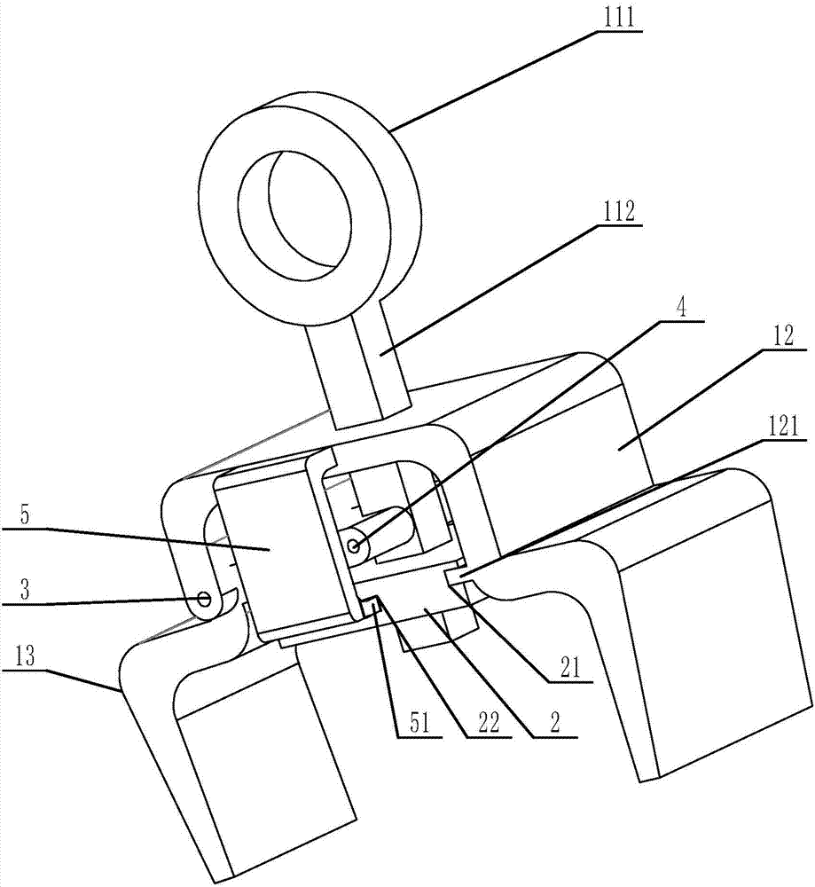
[0036] see figure 1 and image 3 ,

[0037] In this embodiment, the clamping structure 1 of the clamp of the present invention is provided as one, the fixed rod 5 is in the shape of "7", and the end away from the clamping block 51 is fixedly connected to the fixed claw 12, and the magnet 2 is provided with a first groove 21 And the second groove 22, the first groove 21 is fixedly connected with the protrusion 121 on the fixed claw 12, and the second groove 22 is fixedly connected with the block 51 fixedly arranged on the fixed rod 5 on the fixed claw 12 , the first groove 21 and the second groove 22 are arranged on two adjacent surfaces of the magnet 2 .

[0038] The fixture in this embodiment adopts a single jaw structure. Compared with the double jaw structure in Example 1, the structure is simpler and more versatile. When clamping the automobile leaf spring, it should be noted that the automobile plate should be clamped The center of the spring, try to ensure the stabili...

Embodiment 3

[0045] With reference to Example 1, in this embodiment, only the magnet 2 is respectively connected to the groove of the fixed claw 12 and the fixed rod 5, and the fixed clamping connection of the block is changed to use a locking screw to connect the magnet 2 to the fixed clamp respectively. Claw 12, fixed rod 5 locking fixed connection mode. This kind of fixed connection is more firm, and the stability of the fixture is higher.


PUM


Abstract

The invention provides a clamp used for carrying an automobile leaf spring. The clamp comprises a clamping structure and a magnet. The clamping structure comprises a hanger rod, a fixed clamping jaw and a movable clamping jaw. The hanger rod further comprises a lifting ring and a connecting rod, the lifting ring is located at the top of the hanger rod and fixedly connected with one end of the connecting rod, and the connecting rod penetrates through the fixed clamping jaw and the magnet through a through hole in the fixed clamping jaw and a through hole in the magnet. The perpendicular distance between the end face of one end, far away from the lifting ring, of the connecting rod and the magnet is 4cm-8cm. The fixed clamping jaw is shaped like a Chinese character 'gong', the magnet is fixed to the fixed clamping jaw, the movable clamping jaw is M-shaped, the fixed clamping jaw is in hinge joint with the movable clamping jaw through a first hinge joint hole, and the movable clamping jaw is in hinge joint with the connecting rod through a second hinge joint hole which is formed between the fixed clamping jaw and the magnet. One end of the magnet is fixedly connected with the fixed clamping jaw, the other end is fixedly connected with a fixed rod arranged on the fixed clamping jaw, and the magnet is provided with a magnetic resistance switch. The clamp is high in clamping efficiency and automation degree and convenient to operate, and is exclusively used for carrying the automobile leaf spring.

Description

technical field [0001] The invention relates to a clamp specially used for handling leaf springs of automobiles, which belongs to the technical field of machinery. Background technique [0002] Automobile leaf spring is the most widely used elastic element in automobile suspension. It is an elastic beam with approximately equal strength composed of several alloy spring sheets of equal width but unequal length. The shape of the automobile leaf spring has the characteristics of flatness and small surface area per unit volume. The irregular shape makes it inconvenient for traditional clamping tools such as claws to tightly and firmly clamp the automobile leaf spring. [0003] Existing automobile leaf springs are heavy in weight. Generally, when the claws clamp the automobile leaf spring, the automobile leaf spring will slip due to its heavy weight. If the claws with very large clamping force are used, during the clamping process The claws are easy to damage the paint of the au...

Claims


Application Information

Patent Timeline
Patent Type & Authority Applications(China)
IPC IPC(8): B66C1/44B66C1/04
CPCB66C1/04B66C1/44
Inventor 孙毅李仁兵王建忠刘士平王志波
Owner 湖北远成鄂弓汽车悬架弹簧有限公司
Why Eureka
Try Eureka