Near-field direct-writing device based on composite receiving plate

A receiving board and near-field technology, applied in processing platforms/substrates, manufacturing tools, additive manufacturing, etc., can solve problems such as uneven fiber arrangement, achieve the effect of solving uneven distribution and improving positioning accuracy

Active Publication Date: 2017-06-06
NORTHWESTERN POLYTECHNICAL UNIV
View PDF8 Cites 10 Cited by
  • Summary
  • Abstract
  • Description
  • Claims
  • Application Information

AI Technical Summary

Problems solved by technology

[0006] In order to overcome the deficiencies of the prior art, the present invention provides a near-field direct writing device based on a comp

Method used


Image

  • Near-field direct-writing device based on composite receiving plate
  • Near-field direct-writing device based on composite receiving plate

Examples


Example Embodiment

[0035] Specific embodiment one

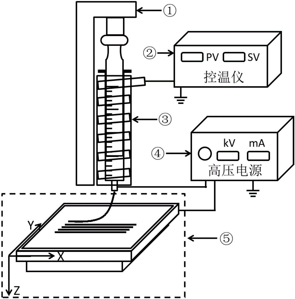
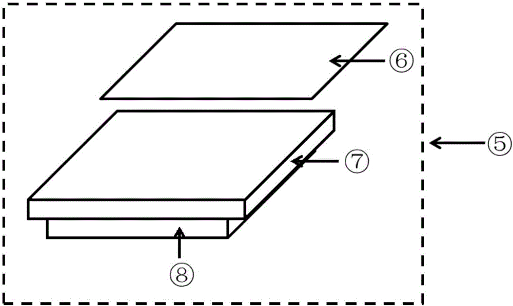
[0036] 1) Fix the insulating layer on the conductive receiving plate to form a new composite receiving plate. Then fix the composite receiving board on the XYZ motion system with a constant temperature control system, so that the composite receiving board can move arbitrarily along the XYZ axis.

[0037] 2) Put the polycaprolactone particles into a glass syringe with a stainless steel needle and heat it to 150°C to melt it, keep it for more than 4 hours and eliminate bubbles, place it on the bolus pump, and adjust the bolus rate to 0.9ml / h; The two ends of the high-voltage power supply are respectively connected to the needle and the conductive receiving plate, so that a high-voltage electric field is formed between the needle and the metal receiving plate; the distance between the composite receiving plate and the needle is adjusted to 5mm, so that the injected droplets are in the high-voltage electric field. Under the action, a tiny stream is for...

Example Embodiment

[0039] Specific embodiment two

[0040] 1) Fix the insulating layer on the conductive receiving plate to form a new composite receiving plate. Then fix the composite receiving board on the XYZ motion system with a constant temperature control system, so that the composite receiving board can move arbitrarily along the XYZ axis.

[0041] 2) Add polycaprolactone to hexafluoroisopropanol to dissolve to form a 15% solution, suck the solution into a 10ml syringe, place it on the bolus pump, adjust the bolus rate to 0.4mm / min; turn on the high-voltage power supply The two ends of the needle are respectively connected with the needle and the conductive receiving plate of the composite receiving plate, so that a high-voltage electric field is formed between the needle and the conductive receiving plate; the distance between the composite receiving plate and the needle is adjusted to 3mm, so that the droplets are injected Under the action of the high-voltage electric field, a tiny jet is f...


PUM


Abstract

The invention provides a near-field direct-writing device based on a composite receiving plate. The near-field direct-writing device based on the composite receiving plate comprises a high-voltage power supply, a pushing injection system, a temperature control system, a movement control system and the composite receiving plate. The pushing injection system is filled with printing materials, and a needle of the pushing injection system perpendicularly points to the surface of the composite receiving plate; the composite receiving plate comprises an electric conductive receiving plate and an insulation layer, and the side, facing the needle, of the electric conductive receiving plate is covered with the insulation layer; the high-voltage power supply is connected with the needle and the electric conductive receiving plate, so that a high-voltage electric field is formed between the needle and the composite receiving plate; the temperature control system controls the temperature of the pushing injection system and the composite receiving plate; and the movement control system controls the composite receiving plate to freely move along an X axis, a Y axis and a Z axis. According to the near-field direct-writing device, flow jetting positioning accuracy in a near-field direct-writing technology can be improved, and consequently, forming accuracy of a 3D printing technology based on the near-field direct-writing technology is improved.

Description

technical field [0001] The invention relates to a near-field direct writing device based on a composite receiving plate, which belongs to the field of microstructure manufacturing. Background technique [0002] Electrospinning technology is the simplest and most convenient method to prepare micro / nanofibers. As early as 1934, Formhals mentioned in a series of patents about the effect of polymer properties on charged fibers on the receiver plate. Subsequently, the research on the preparation of polymer fibers by electrospinning began to receive widespread attention. Under the action of a high-voltage electrostatic field, the polymer droplets first form a stable charged jet, then begin to swing irregularly, and finally form disordered nanofibers that are deposited on the receiving plate. Until 2006, Sun Daoheng and others proposed the near-field direct writing technology, which used a short stable jet to realize the precise deposition process of a single fiber, and opened up...

Claims


Application Information

Patent Timeline
IPC IPC(8): B29C64/112B29C64/245B33Y30/00
CPCB33Y30/00
Inventor 尹大川何凤利张托弟李大为刘雅丽周雅青何进柳洋阳张斌闫二开
Owner NORTHWESTERN POLYTECHNICAL UNIV
Why Eureka
Try Eureka