A kind of processing equipment with waste extrusion function

A technology of processing equipment and functions, applied in the direction of metal processing equipment, metal processing, metal processing machinery parts, etc., can solve the problems of adding extrusion power, difficult collection of processing waste, automatic loading and unloading of processing equipment, etc., to achieve simplification Equipment, adsorption and collection problems are simple, and the effect of automatic clamping is realized

Active Publication Date: 2018-05-15
浙江浦锻货叉制造有限公司
View PDF1 Cites 0 Cited by
  • Summary
  • Abstract
  • Description
  • Claims
  • Application Information

AI Technical Summary

Problems solved by technology

[0006] The purpose of the present invention is to provide a processing equipment with a waste chip extrusion function in view of the shortcomings of the prior art, which overcomes the inability of the processing equipment to realize automatic loading and unloading and the difficulty in collecting processing waste chips, and the troublesome disposal of collected waste chips The need to increase the extrusion power problem

Method used


Image

  • A kind of processing equipment with waste extrusion function
  • A kind of processing equipment with waste extrusion function
  • A kind of processing equipment with waste extrusion function

Examples


Embodiment 1

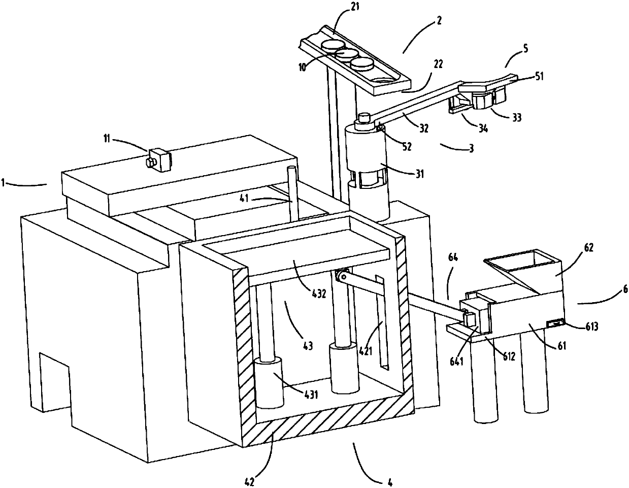
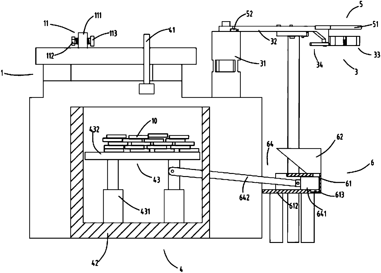
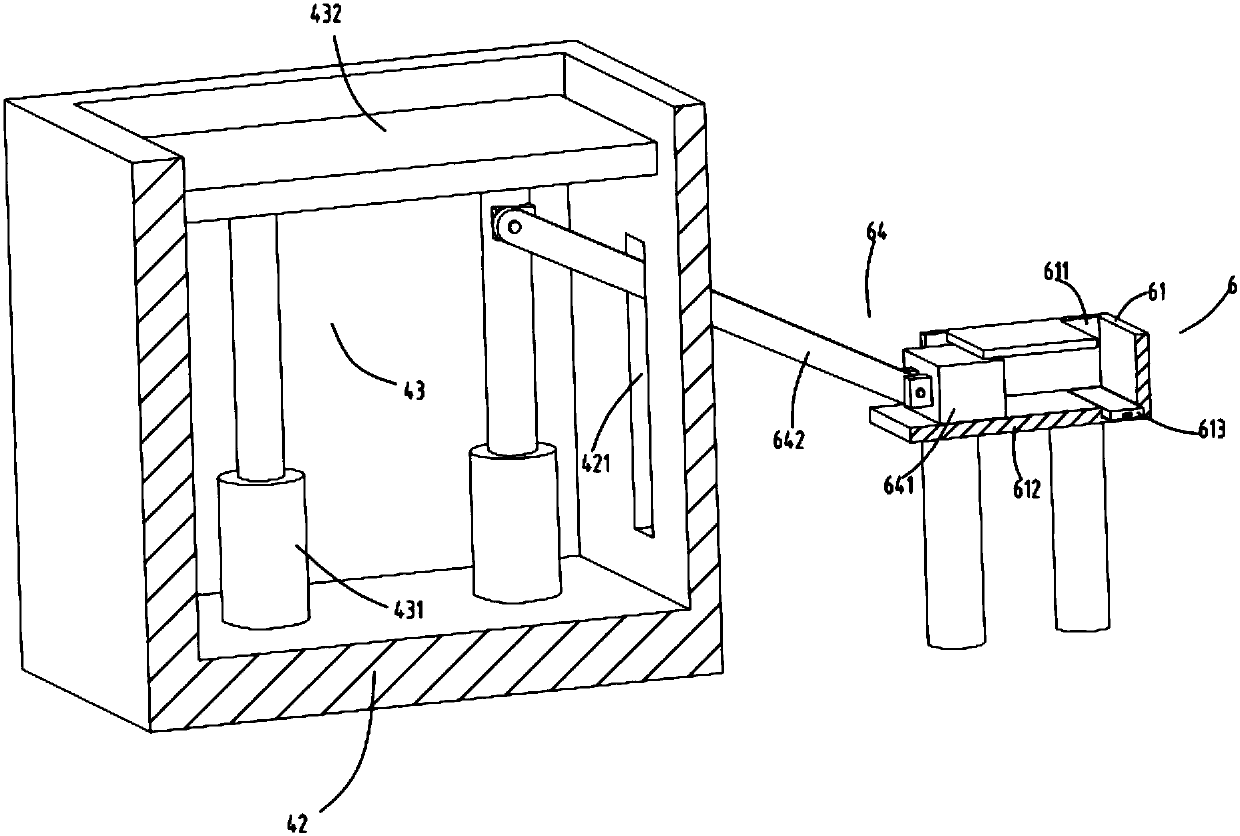
[0039] figure 1 is a schematic diagram of processing equipment with waste extrusion function, figure 2 Schematic diagram of the front view when compressing waste for processing equipment with waste squeezing function, image 3 It is a schematic diagram of the structure of the blanking part and the waste compression collection device, Figure 4 It is a partial structural schematic diagram of the feeding device, Figure 5 It is a schematic diagram of the structure of the feeding part, Figure 6 It is a schematic diagram of the structure of the electromagnetic adsorption head. Such as figure 1 , figure 2 , image 3 , Figure 4 , Figure 5 and Figure 6 As shown, what is provided in this embodiment is a processing equipment with a waste chip extrusion function, including a feeding part 2, a conveying track 21 and a blanking part 22 arranged at the end of the conveying track 21; a feeding device 3, It is used to accept the workpiece 10 falling from the blanking part 22 ...

Embodiment 2

[0056] Such as figure 1 , figure 2 , image 3 , Figure 4 , Figure 5 and Figure 6 As shown, the components that are the same as or corresponding to those in the first embodiment are marked with the corresponding reference numerals in the first embodiment. For the sake of simplicity, only the differences from the first embodiment will be described below. The difference between the second embodiment and the first embodiment is that a guide rod 334 is also provided between the fixed clamp block 331 and the movable clamp block 332, one end of the guide rod 334 is fixed on the fixed clamp block 331, and the other end is relatively movable. The guide groove 3321 provided on the clamp block 332 slides; the elastic member 333 is sheathed on the guide rod 334, and the guide rod 334 can guide the movement of the movable clamp block 332 to prevent it from being squeezed and shifted.

[0057] Workflow: The feeding device 3 feeds at the position of the feeding part 2, and the clamp...


PUM


Abstract

The invention relates to a machining device with a waste scrap extrusion function. The machining device comprises a material supply part, a feeding device, a pressing device and a falling part. The material supply part comprises a conveying track and a falling segment arranged at the tail end of the conveying track. The feeding device comprises a rotation device, a material arm with one end fixed to the rotation device, a material clamping device fixed to the end portion of the material arm, and a material supporting device a rotationally arranged at the bottom of the material clamping device. The pressing device is arranged on the machining device. The falling part comprises a stop lever, a material box arranged below the front end of the stop lever, and a material receiving frame arranged in the material box. The machining device further comprises a waste scrap absorbing device arranged on the rotation device. The waste scrap absorbing device comprises an electromagnetic adsorption head and a power-off sheet. The machining device further comprises a waste scrap compression and collection device. The waste scrap compression and collection device comprises a waste scrap box and a pushing and pressing device extruding waste scraps in the waste scrap box under the action of the material receiving frame. The machining device solves the problems that according to a machining device, automatic feeding and discharging cannot be achieved, the machining waste scraps are hard to collect, the collected waste scraps are troublesome in treatment, and extrusion power needs to be additionally arranged.

Description

technical field [0001] The invention belongs to the technical field of machining equipment, in particular to a processing equipment with waste extrusion function. Background technique [0002] In the process of processing, processing waste will be generated. In the prior art, an air gun is generally used to blow air on the processed workpiece to blow away the waste and then remove the workpiece. In this way, the waste is blown to every corner and cannot be cleaned. Waste chips are effectively recycled, and the loading and unloading of workpieces is generally completed manually, and then processed by clamping, which is more troublesome. [0003] A Chinese utility model patent with the authorized notification number CN204430940U discloses a waste chip recycling device for a drilling machine, which uses an air blowing device to blow the waste chips through the funnel hole into the funnel for recycling, so as to realize the separation of various metal waste chips Recycling redu...

Claims


Application Information

Patent Timeline
Patent Type & Authority Patents(China)
IPC IPC(8): B30B9/32B23Q7/00B23Q11/00
CPCB23Q7/00B23Q11/0064B30B9/32
Inventor 周向荣
Owner 浙江浦锻货叉制造有限公司
Why Eureka
Try Eureka