Electrofluid ink jet printing spray in array and logic control method

A logic control and electrofluidic technology, applied in printing, printing devices, etc., can solve the problems of low printing accuracy, low efficiency, and inability to realize nano-sized printing, and achieve the effect of improving precision, high precision and high efficiency

Pending Publication Date: 2017-06-06
深圳市富彩三维技术有限公司
View PDF16 Cites 18 Cited by
  • Summary
  • Abstract
  • Description
  • Claims
  • Application Information

AI Technical Summary

Problems solved by technology

[0005] The purpose of the present invention is to overcome the problems that the arrayed electrofluid jet printing nozzles in the existing electrofluid jet printing technology cannot realize nano-sized jet printing, can not adjust jet flow diameter on demand, and have low jet printing accuracy and low efficiency; Provided is an arrayed electrofluid jet printing nozzle and a logic control method

Method used


Image

  • Electrofluid ink jet printing spray in array and logic control method
  • Electrofluid ink jet printing spray in array and logic control method

Examples


Embodiment 1

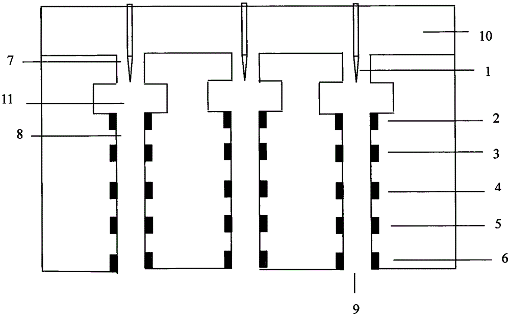
[0033] see figure 1 , the arrayed electrofluid jet printing nozzle is provided with an ink cartridge 10 and three independent orifice systems 11 arranged in an array corresponding to the ink cartridge 10, each independent orifice system 11 includes a feed hole 7, an ejection orifice 9, and the channel 8 between the feed hole 7 and the ejection hole 9, the channel 8 is provided with 6 electrodes, A electrode 1, B electrode 2, C electrode 3, D electrode 4, E electrode 5, F electrode 6. The feed hole 7 of each independent nozzle hole system 11, the nozzle hole 9, the channel 8, the A electrode 1, the B electrode 2, the C electrode 3, the D electrode 4, the E electrode 5, and the F electrode set on the channel 8 The electrodes 6 are distributed on the same axis. The spacing between the electrodes is fixed. Wherein, the A electrode 1 is a needle-shaped electrode, and the B electrode 2 , the C electrode 3 , the D electrode 4 , the E electrode 5 , and the F electrode 6 are ring ele...

Embodiment 2

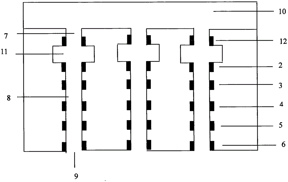
[0040] see figure 2 , the arrayed electrofluid jet printing nozzle is provided with an ink cartridge 10 and three independent orifice systems 11 arranged in an array corresponding to the ink cartridge 10, and each independent orifice system 11 includes a feed hole 7 and an ejection hole 9 , and the channel 8 between the feed hole 7 and the ejection hole 9, the channel 8 is provided with 6 electrodes, G electrode 12, B electrode 2, C electrode 3, D electrode 4, E electrode 5, F electrode 6 , the feed hole 7 of each independent orifice system 11, the ejection hole 9, the channel 8, the G electrode 12, the B electrode 2, the C electrode 3, the D electrode 4, the E electrode 5, and the F electrode arranged on the channel 8 6, for the same axis distribution. The spacing between the electrodes is fixed. Wherein, the G electrode 12, the B electrode 2, the C electrode 3, the D electrode 4, the E electrode 5, and the F electrode 6 are ring electrodes.

[0041] The power supply supp...


PUM


Abstract

The invention discloses an electrofluid ink jet printing spray in array and a logic control method and relates to the technical field of electrofluid ink jet printing. The spray is provided with ink boxes and N independent nozzle systems which are in array arrangement and correspond to the ink boxes. Each independent nozzle system includes a material-in hole, a spray hole, and a channel between the material in hole and the spray hole. The channel is provided with a plurality of electrodes thereon. The method includes the following steps: powering the plurality of electrodes with logic control, applying an electric field to a jet flow with logic control, by regulating the voltages of the electrodes, adjusting the intensity, level, and direction of the electric field, controlling the size, direction and times of the force-bearing of the jet flow. In this way, the logic electric field can effectively control the process of the refining of the jet flow, increases the precision of the refining of the jet flow, not only realizes printing at nanometer, and realizes the adjustment of the diameter of the jet flow according to needs, and is advantaged by high spraying precision and high efficiency.

Description

technical field [0001] The invention relates to the technical field of electrofluid jet printing, in particular to an arrayed electrofluid jet printing nozzle and a logic control method. Background technique [0002] In traditional jet printing technologies based on thermal bubbles or piezoelectric principles, the diameter of the jet stream in the ejection hole is larger than the inner diameter of the ejection hole. Due to the limitation of the processing size, the diameter of the ejection hole of the existing jet printing technology based on thermal bubble or piezoelectric principle is 20-50 microns, and the diameter of the jet is more than 20 microns. Printing to smaller dimensions (such as nanoscale) cannot be achieved. [0003] The electrofluid jet printing technology is based on the electrohydrodynamic effect of the solution or melt. Under the action of the electric field force, it overcomes the surface tension and is stretched to form a stable fine jet with a large di...

Claims


Application Information

Patent Timeline
Patent Type & Authority Applications(China)
IPC IPC(8): B41J2/06B41J2/095B41J2/14B41J29/38
CPCB41J2/06B41J2/095B41J2/14B41J29/38
Inventor 高晓军张亮
Owner 深圳市富彩三维技术有限公司
Why Eureka
Try Eureka