Laser optical path guiding system of laser sinter molding equipment

A laser sintering molding and guiding system technology, applied in laser welding equipment, welding equipment, metal processing equipment, etc., can solve the problems of dust easily setting inside the machine, adverse effects of light path, and high light energy loss, etc. and cooling, improving collimation, and the effect of short optical path

Inactive Publication Date: 2013-05-22
余振新
View PDF6 Cites 16 Cited by
  • Summary
  • Abstract
  • Description
  • Claims
  • Application Information

AI Technical Summary

Problems solved by technology

However, the current laser light path guidance system is prone to drifting light beams, and dust is easy to fall into the machine, which will have a negative impact on the optical path, cause a lot of light energy loss, and make system debugging difficult.

Method used


Image

  • Laser optical path guiding system of laser sinter molding equipment
  • Laser optical path guiding system of laser sinter molding equipment
  • Laser optical path guiding system of laser sinter molding equipment

Examples


Embodiment Construction

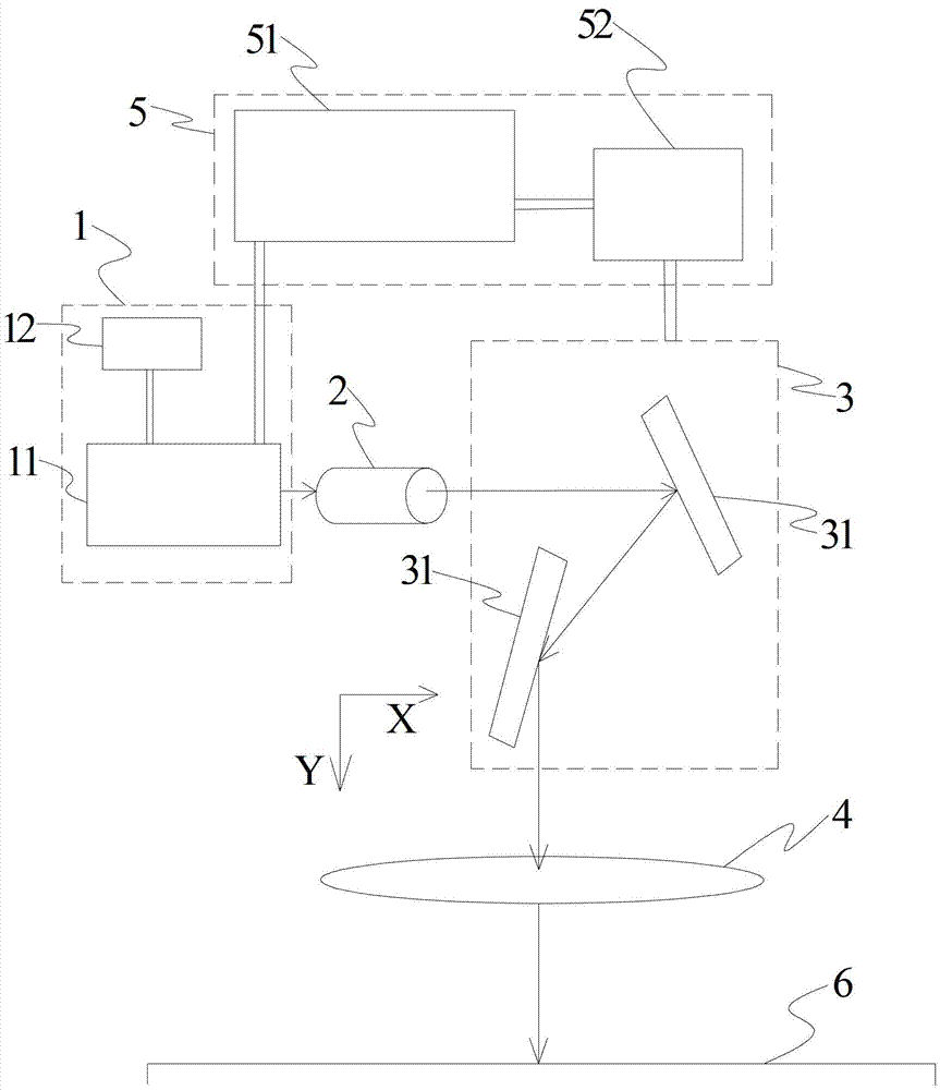
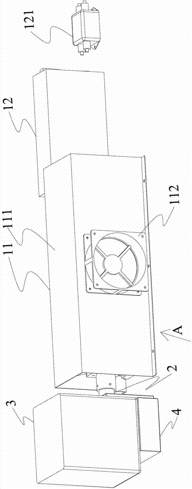
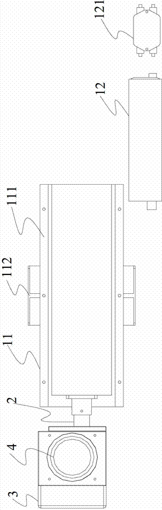
[0032] Such as Figure 1 to Figure 3 The laser optical path guiding system of the laser sintering molding equipment of the shown embodiment includes a laser source 1, a beam expander 2 matched with the laser source, a scanning galvanometer device 3 matched with the beam expander 2 and a scanning galvanometer The flat-field focusing lens 4 connected to the device 3; the laser sintering molding equipment is provided with a molding platform 6, and the flat-field focusing lens 4 is arranged at a position matched with the molding platform 6.

[0033] The laser source 1, the beam expander 2 and the scanning galvanometer device 3 are distributed along the X-axis direction, the flat-field focusing lens 4 and the scanning galvanometer device 3 are distributed along the Y-axis direction; the laser light emitted by the laser source 1 is first along the X-axis After being shot out, the direction is changed by the scanning galvanometer device 3, and shot to the forming platform 6 along the...


PUM


Abstract

The invention discloses a laser optical path guiding system of laser sinter molding equipment. The laser optical path guiding system of the laser sinter molding equipment comprises a laser source, a beam expander matched with the laser source, a scanning galvanometer device matched with the beam expander and a flat field focusing lens connected with the scanning galvanometer device. The laser sinter molding equipment is provided with a molding platform, a focal plane of the flat field focusing lens is overlapped with the molding platform, and the focus point of the lens is arranged at the center of the molding platform. Due to the mentioned structure, not only can printing of a three-dimensional component be achieved very well, but also each optical component can be connected into a whole without clearances, drifting of light beams is avoided, at the same time dust and vibration are prevented. In addition, protection of optical elements like the galvanometers and the like is considered. The laser optical path guiding system is compact in structure, short in optical path, small in light energy consumption, and convenient to debug.

Description

technical field [0001] The invention relates to the field of selective laser sintering forming technology equipment at normal temperature, in particular to the laser light path guiding system of laser sintering forming equipment Background technique [0002] SLS technology (SLS: Selective Laser Sintering, selective laser sintering of powder materials) is a rapid prototyping process, which spreads material powder on the upper surface of the formed part and scrapes it; uses a high-intensity CO2 laser on the newly laid The cross-section of the part is scanned on the new layer; the material powder is sintered together under high-intensity laser irradiation to obtain the cross-section of the part and connected with the formed part below; when the cross-section of one layer is sintered, a new layer is laid Powder material, selectively sintered lower section. All in all, SLS technology uses laser to selectively sinter solid powder in layers, and makes the sintered solidified layer...

Claims


Application Information

Patent Timeline
Patent Type & Authority Applications(China)
IPC IPC(8): B23K26/06B22F3/105B23K26/064B23K26/082
CPCY02P10/25
Inventor 余振新
Owner 余振新
Why Eureka
Try Eureka