
Station arrangement structure of idling motor automatic final inspecting and labeling integrated machine

An idle motor and automatic technology, applied to typewriters, conveyor objects, printing, etc., can solve the problems of low work efficiency, loss of manufacturers and consumers, and high labor costs, and achieve the effect of improving work efficiency and saving labor costs

Inactive Publication Date: 2017-06-06
温州博诚汽车机电有限公司
View PDF7 Cites 2 Cited by
  • Summary
  • Abstract
  • Description
  • Claims
  • Application Information

AI Technical Summary

Problems solved by technology

[0002] The idle speed motor is a component that controls the idle speed of the motor vehicle. Its function is to change the cross-sectional area of ​​the idle air passage according to the engine temperature and load when the vehicle is idle, so that the engine has the best idle speed under different conditions. Therefore, there are relatively high quality requirements. After the manufacture of this kind of motor, it is necessary to conduct a 100% full inspection of its key performances such as air tightness, concentricity, resistance, thrust and lost steps. The existing test equipment is simple in structure, Scattered, requires multiple operators to operate, high labor cost, low work efficiency, and at the same time, due to manual operation, there are often missed inspections, misplaced products, that is, unqualified products are mistakenly put into qualified products, resulting in the use of unqualified products. Manufacturers and consumers cause losses

Method used


Image

  • Station arrangement structure of idling motor automatic final inspecting and labeling integrated machine
  • Station arrangement structure of idling motor automatic final inspecting and labeling integrated machine

Examples


Embodiment Construction

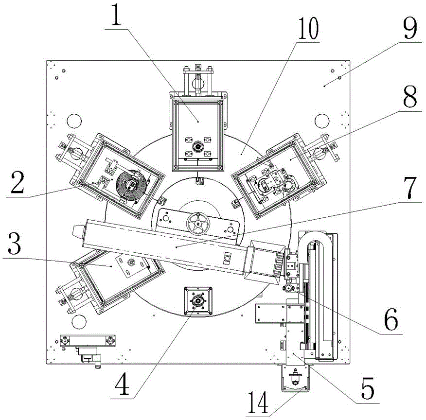
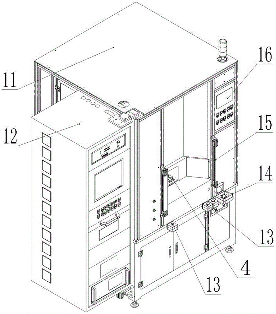
[0010] Such as figure 1 with figure 2 Shown: an idle motor automatic final inspection and marking integrated machine station arrangement structure, including turntable 10, air tightness detection device 3, concentricity detection device 2, resistance detection device 1, thrust and lost step detection device 8, Marking device 7, blanking device 6, turntable 10 is set on bottom plate 9, turntable 10 is provided with a number of product clamps 4, in this embodiment air tightness detection device 3, concentricity detection device 2, resistance detection device 1. Thrust and lost step detection device 8, marking device 7 and blanking device 6 are arranged on the bottom plate 9 around the turntable 10 and corresponding to the position of the product clamp 4, and a blanking slide 5 is provided behind the blanking device 6.

[0011] Among them, a material box 14 is connected after the material chute 5.

[0012] Among them, the outer periphery of the bottom plate 9 is provided with a safe...


PUM


Abstract

The invention discloses a station arrangement structure of an idling motor automatic final inspecting and labeling integrated machine. The station arrangement structure comprises a turnplate, an airtightness detection device, a concentricity detection device, a resistance detection device, a thrust and asynchronization detection device 8, a labeling device and a discharging device. The turnplate is arranged on a bottom plate. A plurality of product clamps are arranged on the turnplate. The airtightness detection device, the concentricity detection device, the resistance detection device, the thrust and asynchronization detection device, the labeling device and the discharging device surround the turnplate, are arranged on the bottom plate and correspond to the product clamps in positions. A discharging chute is arranged behind the discharging device. According to the station arrangement structure, the problem that ordinary testing equipment needs a large amount of labor for operation is solved; testing techniques are integrated into one piece of equipment, only one person is needed for operation, the working efficiency is improved, and labor cost is reduced; and in addition, in the detection process, man-made operation factors are avoided, and the test consistency is guaranteed.

Description

Technical field [0001] The invention relates to the field of idle speed motor detection, in particular to a station arrangement structure of an idle speed motor automatic final inspection and marking integrated machine. Background technique [0002] The idle speed motor is a component that controls the idle speed of a motor vehicle. Its function is to change the cross-sectional area of ​​the idle air passage according to the engine temperature and load when the vehicle is idling, so that the engine has the best idle speed under different conditions. Therefore, there are relatively high quality requirements. After this kind of motor is manufactured, it needs to perform a 100% full inspection of its key properties such as air tightness, concentricity, resistance, thrust and lost step. The existing test equipment has a simple structure. Dispersion, requires multiple operators to operate, high labor cost and low work efficiency. At the same time, due to manual operation, there are of...

Claims


Application Information

Patent Timeline
IPC IPC(8): B65G47/90B65G47/248G01D21/02B41J3/407
CPCG01D21/02B65G47/248B65G47/904B65G47/907B41J3/4073
Inventor 黄正战
Owner 温州博诚汽车机电有限公司
Learn More