Heating furnace convenient to clean and maintain and high in energy efficiency

A heating furnace and high energy-efficiency technology, applied in the field of heating furnaces, can solve the problems of large manual labor, low utilization rate of heat energy, inability to disassemble, etc., and achieve the effects of timely cleaning and replacement, high utilization rate of heat energy, and easy disassembly and assembly.

Pending Publication Date: 2017-06-06
东莞市创威自动化科技有限公司 +1
View PDF5 Cites 1 Cited by
  • Summary
  • Abstract
  • Description
  • Claims
  • Application Information

AI Technical Summary

Problems solved by technology

[0002] At present, the structure of the heating furnace in SMT is: 1. The heating tube is embedded in the partition for heating. When heating, the partition needs to be heated first, and then the furnace body is heated. The utilization rate of heat energy is low, and the insulation between the heating tube and the furnace body The board is integrated and cannot be disassembled
2. The screws of the cooling bottom box are locked, it is difficult to disassemble and clean, the assembly steps are cumbersome, and the amount of manual labor is large

Method used


Image

  • Heating furnace convenient to clean and maintain and high in energy efficiency
  • Heating furnace convenient to clean and maintain and high in energy efficiency
  • Heating furnace convenient to clean and maintain and high in energy efficiency

Examples


Embodiment Construction

[0021] The present invention will be further described below according to the accompanying drawings and specific embodiments, but the embodiments of the present invention are not limited thereto.

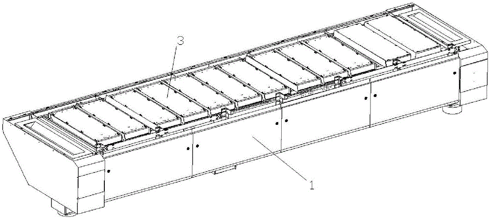
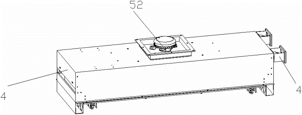
[0022] Such as figure 1 , figure 2 , image 3 , Figure 4 , Figure 5 and Figure 6 As shown, a heating furnace that is easy to clean and maintain and has high energy efficiency includes a hearth 1 with the same structure at the feed end and the discharge end. The upper plane of the hearth 1 is provided with a plurality of heating chambers 2 at intervals, and each heating chamber 2 The upper end of each is covered with a partition plate 3 that can be slid to open or slid to lock, and the bottom of the heating furnace chamber 2 is provided with a heating tube assembly 4 that can be pulled out horizontally from the bottom of the heating furnace chamber 2 or pushed into and clamped horizontally. A radiator plate 5 is used to separate the bottom of the furnace chamber 2 from the h...


PUM


Abstract

The invention discloses a heating furnace convenient to clean and maintain and high in energy efficiency. The heating furnace comprises a furnace platform of which the feeding end and the discharging end are the same in structure. A plurality of heating furnace cavities are formed in the upper plane of the furnace platform at intervals. A partition plate which can be slidably opened or slidably clamped covers the upper end of each heating furnace cavity. The bottom of each heating furnace cavity is provided with a heating pipe assembly which can be horizontally pulled out from or horizontally pushed into the bottom of the heating furnace cavity to be clamped. The bottom of each heating furnace cavity and the corresponding heating pipe assembly are partitioned through a heat dissipation plate. By means of the structure design, easy disassembling and assembling can be achieved without the step of disassembling screws. According to the heating furnace convenient to clean and maintain and high in energy efficiency, heating pipes which can be horizontally inserted and installed are designed and directly heat air in heating pipe installation cavities; hot air is brought to the heating cavities through heat dissipation fans; through the air direct heating mode, the steps that the partition plates are heated at first, and then heat energy is transmitted to air are not needed, and the heat energy utilization rate is higher; and in addition, the heating pipes are convenient to disassemble and can be timely cleaned and replaced.

Description

technical field [0001] The invention relates to the field of SMT, in particular to a heating furnace that is easy to clean and maintain and has high energy efficiency. Background technique [0002] At present, the structure of the heating furnace in SMT is: 1. The heating tube is embedded in the partition for heating. When heating, the partition needs to be heated first, and then the furnace body is heated. The utilization rate of heat energy is low, and the insulation between the heating tube and the furnace body The board is one piece and cannot be disassembled. 2. The screws of the heat dissipation bottom box are locked, it is difficult to disassemble and clean, the assembly steps are cumbersome, and the amount of manual labor is large. Contents of the invention [0003] The object of the present invention is to provide a heating furnace that is easy to clean and maintain and has high energy efficiency, aiming at the above-mentioned defects of the prior art. [0004] ...

Claims


Application Information

Patent Timeline
Patent Type & Authority Applications(China)
IPC IPC(8): F27B17/00F27D11/02F27D1/18
CPCF27B17/0083F27D1/1808F27D11/02F27B2017/0091
Inventor 贾夫振王军涛苏金财
Owner 东莞市创威自动化科技有限公司
Why Eureka
Try Eureka