image display device

An image display device and image technology, applied in projection devices, instruments, optics, etc., can solve problems such as different brightness

Active Publication Date: 2019-09-27
HONDA MOTOR CO LTD +1
View PDF7 Cites 0 Cited by
  • Summary
  • Abstract
  • Description
  • Claims
  • Application Information

AI Technical Summary

Problems solved by technology

[0005] However, in the technology described in Patent Document 1, a half mirror is used, so the brightness of the image that can be visually recognized by the driver and the passenger sometimes differs.
[0006] In addition, in the technology described in Patent Document 2, the second diffracted light is obtained by the holographic optical element of the second layer after passing through the first layer, and therefore, the image that can be visually recognized by the first diffracted light and the second diffracted light may be The brightness is different

Method used


Image

  • image display device
  • image display device
  • image display device

Examples


no. 1 Embodiment approach

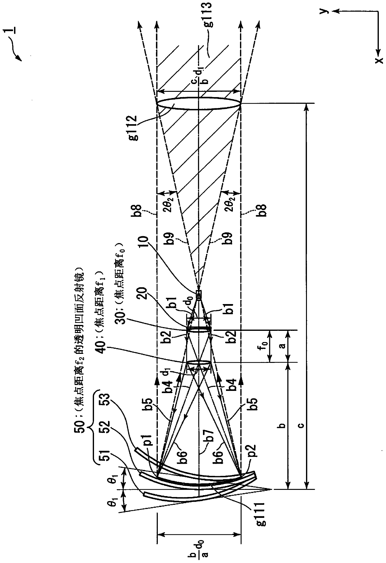
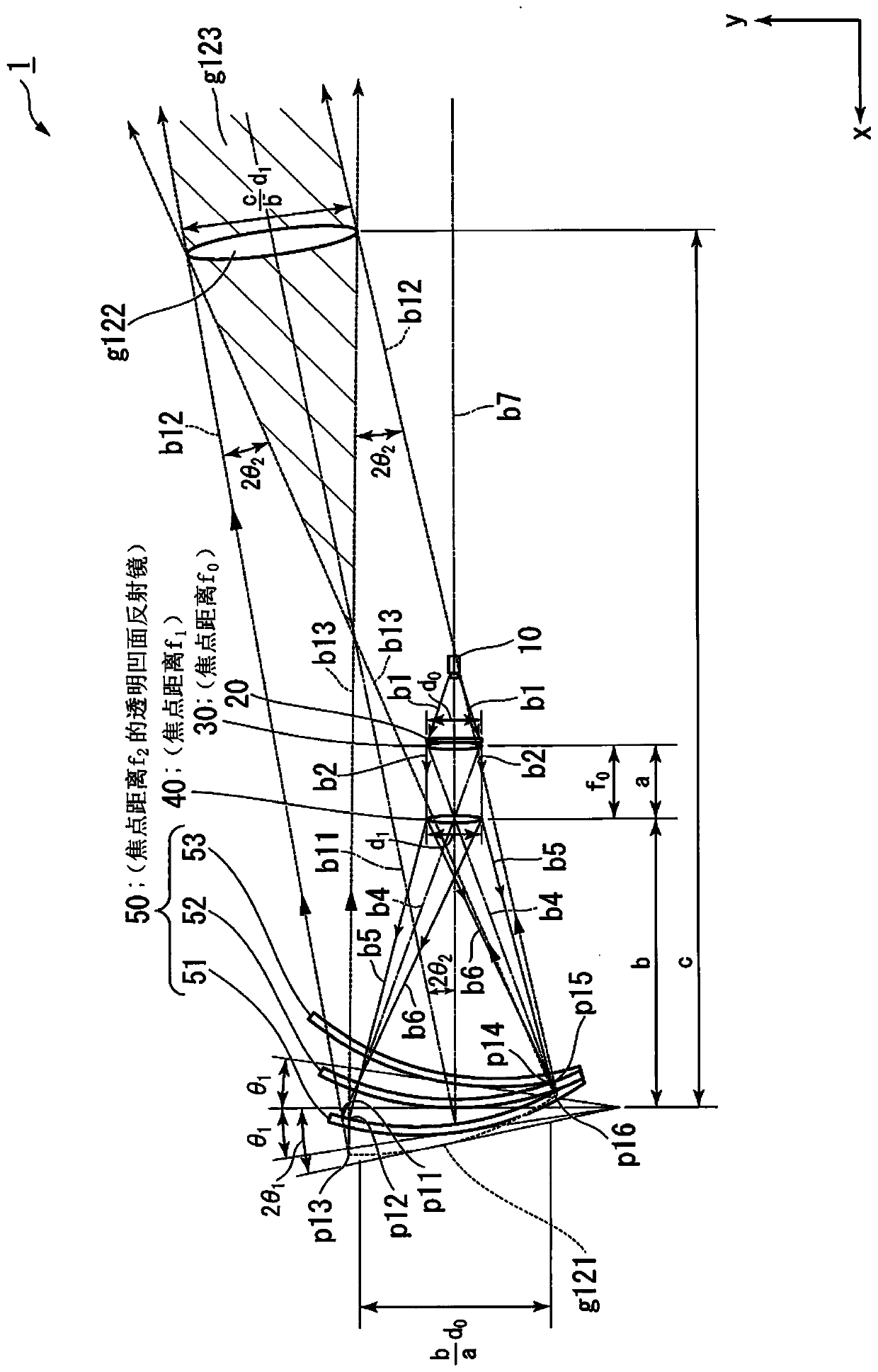
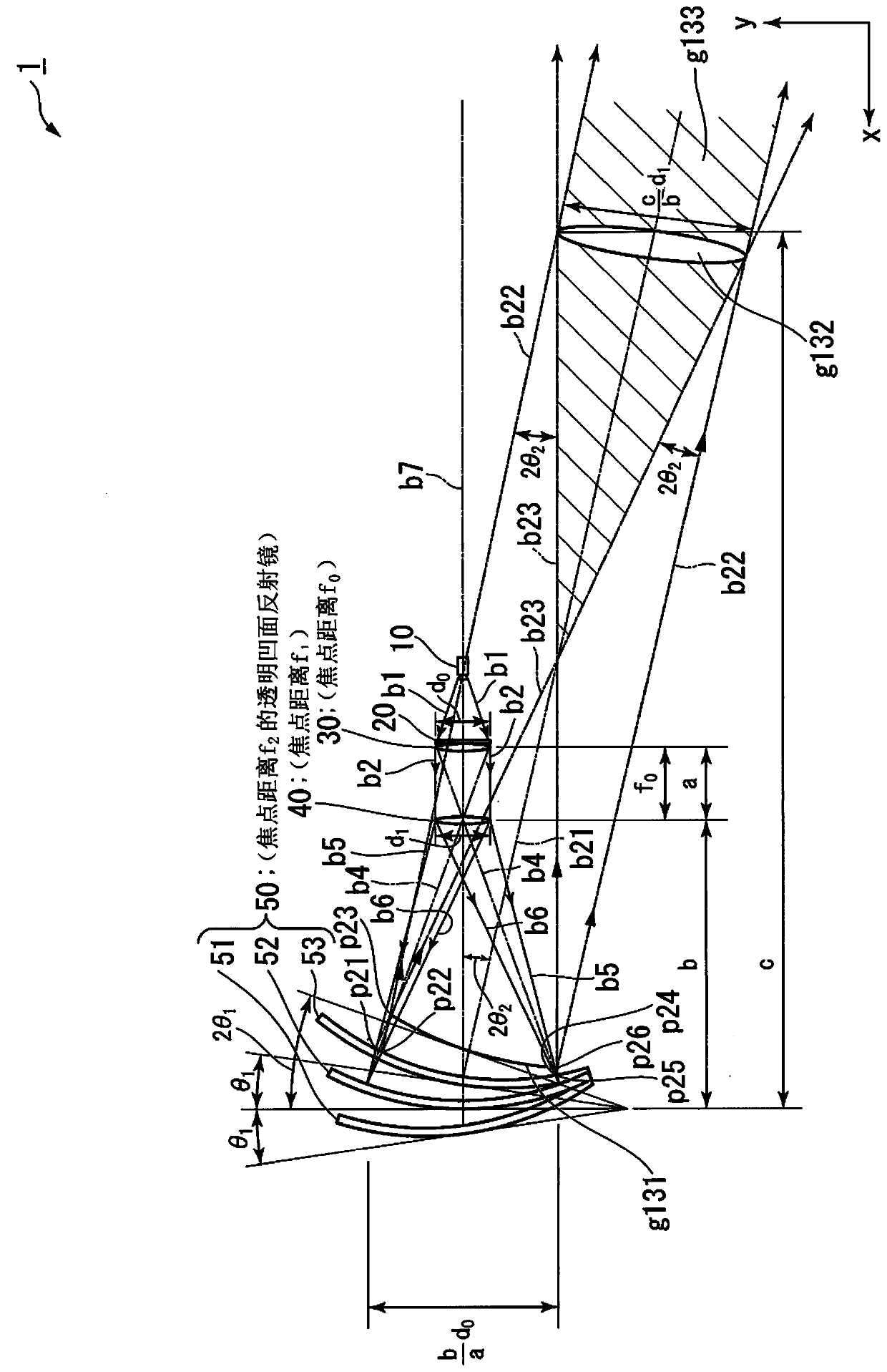
[0066] figure 1 It is a diagram showing the configuration of the image display device 1 according to the present embodiment and the spatial imaging iris plane g112 formed based on the real image g111 of the second combiner 52 . figure 2 It is a diagram showing the configuration of the image display device 1 according to the present embodiment and the spatial imaging iris surface g122 formed based on the virtual image g121 of the first combiner 51 . image 3 It is a diagram showing the configuration of the image display device 1 according to the present embodiment and the spatial imaging iris surface g132 formed based on the aerial image g131 of the third combiner 53 . Figure 4 is synthetic Figure 1 ~ Figure 3 get the graph.

[0067]

[0068] Such as Figure 1 ~ Figure 4 As shown, the image display device 1 includes a projector 10 (projection unit), a diffusion film 20 (projection unit), a condenser lens 30 (projection unit), an imaging lens 40 (projection unit) and a m...

no. 2 Embodiment approach

[0213] In the first embodiment, an example of the image display device 1 in which a real image is formed on the second combiner 52 has been described.

[0214] When the image display device 1 is mounted on a vehicle, the observer focuses on the scenery of the outside world observed through the first combiner 51 to the third combiner 53 . In the image display device 1 of the first embodiment, when observing the displayed image information, the observer needs to focus on Figure 1 ~ Figure 4 The virtual, real, or aerial image shown.

[0215] Therefore, in this embodiment, an example in which a virtual image is formed by all the combiners at positions in the background direction of the combiners will be described. In this way, if a virtual image is displayed at a position about 1 m behind the combiner, the observer can observe the displayed image with little adjustment of the lens.

[0216] Figure 9 It is a diagram showing the configuration of the image display device 1A acco...

no. 3 Embodiment approach

[0270] In the first embodiment and the second embodiment, examples in which the first combiner 51 to the third combiner 53 are transparent concave mirrors have been described.

[0271] In the present embodiment, an example will be described in which the surface or the back surface of the first combiner 51 disposed on the rearmost side is painted or vapor-deposited in black, for example.

[0272] First, an example in which the front or back of the first combiner 51 disposed at the rearmost side of the image display device 1 according to the first embodiment is painted or deposited in black, for example, will be described.

[0273] Figure 13 It shows the structure of the image display device 1C according to this embodiment, the spatial imaging iris surface g112 by the second combiner 52, the spatial imaging iris surface g122 by the first combiner 51c, and the spatial imaging iris surface by the third combiner 53. Diagram of g132. in addition, Figure 13 The illustrated examp...


PUM


Abstract

An image display device comprising: a projection unit that projects an image; a plurality of concave mirrors arranged such that their contact surfaces with the optical axis are at different angles to each other with respect to the optical axis of the projection unit, The first concave mirror among the plurality of concave mirrors reflects at least part of the image projected by the projection unit to form a first image based on the image, and the second concave mirror among the plurality of concave mirrors transmits the image projected by the projection unit A part of and reflects a part of the image to form a second image based on the image.

Description

technical field [0001] The invention relates to an image display device. Background technique [0002] We have developed a HUD (Head-Up Display) that overlaps driving information with the driver's field of view and displays it on the front windshield of the vehicle. The driving information refers to, for example, information related to speed and car navigation. In the conventional HUD, since the field of view is narrow, both the driver and the passenger seated in the passenger seat cannot visually recognize vehicle information. [0003] Therefore, such a display device has been proposed: a half mirror is arranged between the display body and the display unit to change the angle of the display surface on which the image is displayed, whereby the driver and the passenger can visually recognize the driving information (for example, Refer to Japanese Utility Model Laid-Open Publication No. Sho 63-158428 (hereinafter referred to as Patent Document 1)). In addition, the display...

Claims


Application Information

Patent Timeline
Patent Type & Authority Patents(China)
IPC IPC(8): G03B21/28G02B27/01
CPCG02B27/0101G03B21/28G02B5/02G02B2027/0118G02B13/16G02B27/0172G02B27/0176G02B2027/0123G02B2027/013G02B2027/0159
Inventor 川上徹篠井六弥铃木芳人荒木俊行大平力
Owner HONDA MOTOR CO LTD
Why Eureka
Try Eureka