Multi-sensor system for inspection robot and inspection method

An inspection robot and multi-sensor technology, applied in manipulators, manufacturing tools, etc., can solve problems such as difficulty in ensuring real-time performance, large amount of data, and low GPS accuracy.

Active Publication Date: 2017-06-09
SHENYANG INST OF AUTOMATION - CHINESE ACAD OF SCI +1
View PDF8 Cites 20 Cited by
  • Summary
  • Abstract
  • Description
  • Claims
  • Application Information

AI Technical Summary

Problems solved by technology

[0003] At present, Li Qiang provides global information of the route environment based on GPS and prior knowledge of the route. However, due to the low accuracy of GPS and inaccurate prior knowledge, the positioning accuracy of the robot for obstacles is low, and the unknown route environment cannot be detected. Obstacles [Li Qiang. Design of optical cable positioning and inspection system based on GPS technology. Journal of Lanzhou Jiaotong University (Natural Science Edition), 2007,26(3): 116-118.]; Huang Xiaorong et al. solved the local environment based on laser sensors However, the positioning and recognition of obstacles cannot be realized globally or in a larger range [Huang Xiaorong, Ruan Yi, Li Zheng, Tang Yanyan. Research on Space Inspection Method of 500kV EHV Overhead Transmission Line Inspection Robot [J]. Machine Tools and Hydraulics, 2011, 39(11): 36-39.]; Hu Caishi et al. provided more environmental information based on visible light vision, but the algorithm adopted generally has a large amount of data and complex calculations, which is difficult to guarantee Real-time [Hu Caishi, Wu Gongping, Cao Xi, etc. Research on visual detection and recognition of obstacles in high-voltage transmission line inspection robots. Journal of Sensing Technology, 2008, 21(12): 2092-2096.]

Method used


Image

  • Multi-sensor system for inspection robot and inspection method
  • Multi-sensor system for inspection robot and inspection method
  • Multi-sensor system for inspection robot and inspection method

Examples


Embodiment Construction

[0087] The present invention will be further described in detail below in conjunction with the accompanying drawings and embodiments.

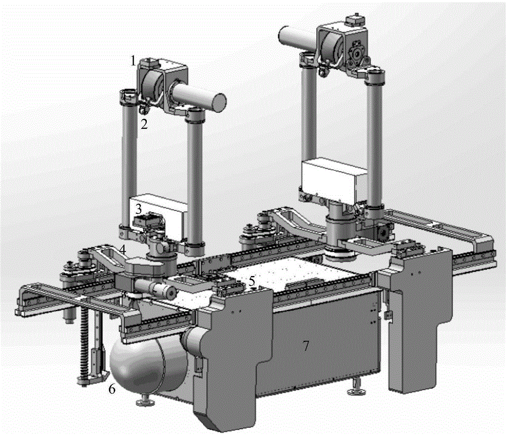
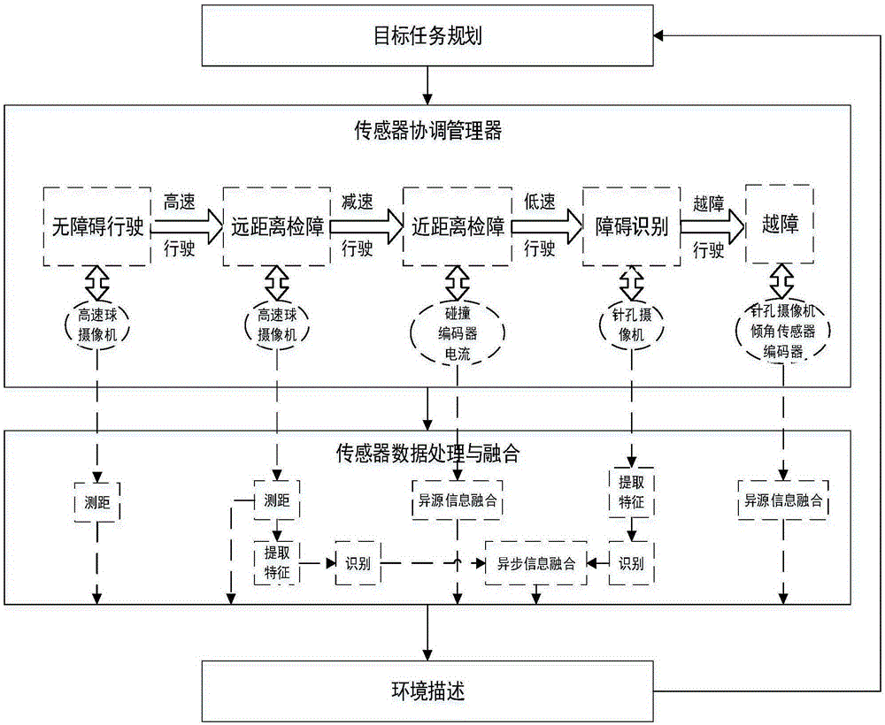
[0088] The inspection robot multi-sensor system consists of internal sensors (encoders, current sensors, temperature sensors, limit sensors, inclination sensors, battery power sensors, etc.) that feed back the state of the robot and external sensors (vision sensors and contact sensors) that perceive the environment. Encoders, current sensors, temperature sensors, and limit sensors are installed at each joint motor to feed back the state of each joint of the robot; the inclination sensor feeds back the overall inclination angle of the robot; the battery power sensor is used to detect and estimate the remaining battery power of the robot; the contact sensor consists of It consists of collision switches installed at both ends of the walking wheels; the visual sensor includes a pan-tilt camera installed at the front of the robot and a pinhole camer...


PUM


Abstract

The invention relates to a multi-sensor system for an inspection robot and an inspection method. The multi-sensor system is characterized in that a sensor system acquires the current state of the inspection robot and external environmental information and sends the acquired current state and external environmental information to a ground base station; and after receiving the current state of the inspection robot and the external environmental information, which are sent by the sensor system, the ground base station sends a control command to the inspection robot. The problem that comprehensive and accurate environmental information of a power transmission line are very difficult to acquire in the driving process of the inspection robot is solved, and autonomous line catching and dynamic centroid adjustment in the obstacle crossing process of the inspection robot are guaranteed.

Description

technical field [0001] The invention relates to the field of robot inspection control, in particular to a multi-sensor system and inspection method of an inspection robot. Background technique [0002] The inspection robot moves along the overhead ground wire or transmission wire, and the anti-vibration hammers, wire clamps, crimping tubes, and spacers installed on it are all obstacles that the robot must cross during the inspection process. Therefore, when the inspection robot is running on the line, it is necessary to detect the line environment ahead, especially to analyze the obstacles existing on the line ahead, to determine its shape, size and position on the line, so as to guide the robot to stabilize its trend. approach and cross these obstacles. The inspection robot mainly realizes the understanding of the line environment by sensing the external environment information through sensors. [0003] At present, Li Qiang provides global information of the route environ...

Claims


Application Information

Patent Timeline
Patent Type & Authority Applications(China)
IPC IPC(8): B25J13/08B25J19/04
Inventor 王洪光张成巍姜勇张珏李贞辉许继葵李瀚儒罗红伍衡宁宇
Owner SHENYANG INST OF AUTOMATION - CHINESE ACAD OF SCI
Why Eureka
Try Eureka