A new energy vehicle charging device

A new energy vehicle and charging device technology, which is applied in electric vehicle charging technology, charging stations, electric vehicles, etc., can solve the problems of electric shock, easy generation of electric arc, poor plug stability and other problems, so as to prevent electric shock accidents and reduce operation Steps, the effect of improving work efficiency

Inactive Publication Date: 2017-12-19
深圳龙电华鑫控股集团股份有限公司
View PDF4 Cites 0 Cited by
  • Summary
  • Abstract
  • Description
  • Claims
  • Application Information

AI Technical Summary

Problems solved by technology

However, in the existing technology, the ordinary car charging plug is prone to arc due to the influence of voltage during the plugging and unplugging process, and the generation of arc is likely to cause electric shock to the user. There is a problem of poor plug stability and easy loosening

Method used


Image

  • A new energy vehicle charging device
  • A new energy vehicle charging device
  • A new energy vehicle charging device

Examples


Embodiment Construction

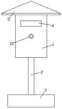
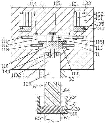
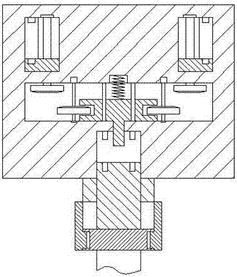
[0021] like Figure 1-Figure 6 As shown, a new energy vehicle charging device of the present invention includes a charging box 1, a support rod 2, a fixing seat 3 and a charging joint 6, and the front end of the charging box 1 is provided with an external thread connector 12. There is a through hole 120 inside the externally threaded connector 12 , and an insertion hole 14 is arranged in the charging box 1 behind the through hole 120 , and a conductive insertion rod 140 is arranged on the inner wall of the rear side of the insertion hole 14 . The charging box 1 behind the socket hole 14 is provided with a first cavity 11 , the rear inner wall of the first cavity 11 is provided with a sinking groove 115 , and the first sinking groove 115 on the front side A moving block 110 is arranged in a cavity 11, and a pressing spring 1151 is arranged between the rear end surface of the moving block 110 and the sinker 115, and the first cavity 11 on both sides of the pressing spring 1151 ...


PUM


Abstract

The invention discloses a high-safety new energy automobile charging device which comprises a charging box, a supporting rod, a fixing base and a charging connector. An external thread connecting piece is arranged on the front end face of the charging box. A through hole is formed inside the external thread connecting piece. A pluggable hole is formed in the portion, on the rear side of the through hole, inside the charging box. A conductive insertion rod is arranged on the inner wall of the rear side of the pluggable hole. A first cavity is arranged in the portion, behind the pluggable hole, inside the charging box. A sediment groove is formed in the inner wall of the rear side of the first cavity. A movable block is arranged inside the first cavity on the front side of the sediment groove. A top pressure spring is arranged between the sediment groove and the end face of the rear side of the movable block. Guide rods are symmetrically arranged at the portions, on the two sides of the top pressure spring, inside the first cavity. The guide rods are connected with the movable block in a sliding-fit mode. The front end side of the movable block is provided with a top pressure rod penetrating through the inner wall of the charging box and stretching into the pluggable hole. Grooves are formed in the end walls of the left and right sides of the movable block. Spline rotating shafts are symmetrically arranged at the portion, on the outer side of the movable block, inside the first cavity, and the rear side ends of the spline rotating shafts are in power connection with a motor. The automobile charging device is simple in structure, stable in charging connection and high in safety.

Description

technical field [0001] The invention relates to the technical field of new energy vehicle charging, in particular to a new energy vehicle charging device. Background technique [0002] With the increasingly urgent task of energy saving and emission reduction, electric vehicles have been promoted on a large scale. However, in the process of consumption and use of electric vehicles, there is still a lot of room for improvement in the improvement of supporting charging facilities. Although the above electric vehicle charging piles can provide convenient and fast charging functions for car owners in parking lots, residential areas, highway rest areas, etc., provide strong support for the long-lasting battery life of electric vehicles, and completely solve the problem of insufficient battery life of electric vehicles. However, in the existing technology, the ordinary car charging plug is prone to arc due to the influence of voltage during the plugging and unplugging process, and...

Claims


Application Information

Patent Timeline
Patent Type & Authority Patents(China)
IPC IPC(8): B60L11/18
CPCB60L53/16Y02T10/70Y02T10/7072Y02T90/14
Inventor 汪俊
Owner 深圳龙电华鑫控股集团股份有限公司
Why Eureka
Try Eureka