Supercharge Your Innovation With Domain-Expert AI Agents!

Conductor rail transition connection device

A transitional connection and conductor rail technology, applied in the field of vehicle engineering, can solve problems such as damage to collector shoes, burn collector shoes, damage collector shoes, etc., so as to reduce the failure rate, reduce maintenance costs, and prevent the effect of connecting circuits.

Active Publication Date: 2017-11-17
BYD CO LTD
View PDF5 Cites 0 Cited by
  • Summary
  • Abstract
  • Description
  • Claims
  • Application Information

AI Technical Summary

Problems solved by technology

[0002] The conductive rail in the related art adopts the arrangement of transitional bends at the turnout, which causes electrical discontinuity between the sections, which will cause the power loss at each fracture when the train passes the turnout, resulting in unstable flow of the train. When the collector shoe is separated from the end elbow, it is easy to generate an arc, which may burn the collector shoe. On the other hand, when the collector shoe slides on the end, it will have an impact with the end elbow, which may damage the collector shoe. Moreover, the conductive track There is a transitional hard point at the turning point of the fork beam, and the collector shoe will be greatly impacted when passing through the hard point. When the tire of the traveling wheel bursts, the overall sinking of the train will cause damage to the collector shoe, and even cause a train accident.

Method used


Image

  • Conductor rail transition connection device
  • Conductor rail transition connection device
  • Conductor rail transition connection device

Examples


Embodiment Construction

[0065] Embodiments of the present invention are described in detail below, examples of which are shown in the drawings, wherein the same or similar reference numerals designate the same or similar elements or elements having the same or similar functions throughout. The embodiments described below by referring to the figures are exemplary and are intended to explain the present invention and should not be construed as limiting the present invention.

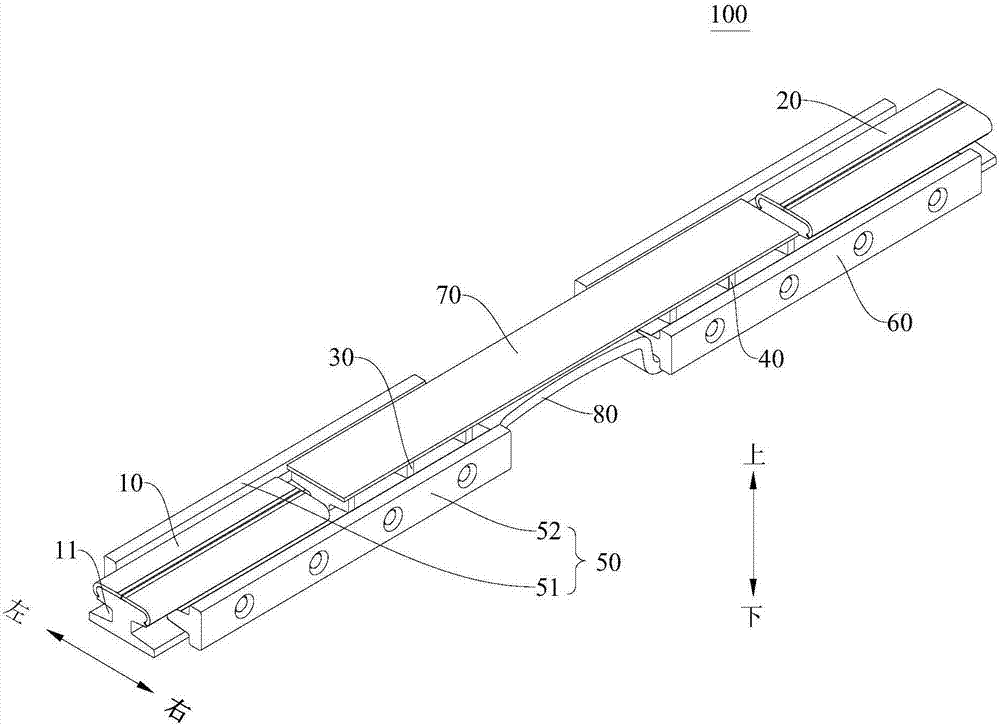
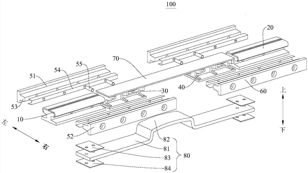
[0066] Attached below figure 1 to attach Figure 15 The conductor rail transition connection device 100 according to the embodiment of the present invention will be described in detail.

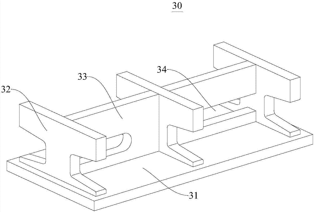
[0067] The conductive rail transition connection device 100 according to the embodiment of the present invention includes: a first conductive rail 10, a second conductive rail 20, a first base 30, a second base 40, a first limiting splint 50, a second limiting splint 60, Flexible transition plate 70 and current connector 80 .

[0068] Specifi...


PUM


Abstract

The invention discloses a conductive rail transition connection device. The conductive rail transition connection device includes a first conductive rail, a second conductive rail, a first base, a second base, first limiting clamping plates, second limiting clamping devices, a flexible transition plate, and a current connector; cross sections of the first conductive rail and the second conductive rail are substantially H-shaped; the first conductive rail and the second conductive rail are arranged at an interval in the axial direction; the first base and the second base are arranged between the first conductive rail and the second conductive rail, the first base is near the first conductive rail, and the second base is near the second conductive rail; the first limiting clamping plates are arranged on two sides of the first conductive rail and the first base so as to fix the first conductive rail and the first base; two ends of the flexible transition plate are connected to the first base and the second base respectively; the current connector is connected to the first conductive rail and the second conductive rail so as to achieve an electrical connection between the first conductive rail and the second conductive rail. The conductive rail transition connection device is excellent in stability and reliability.

Description

technical field [0001] The invention relates to the technical field of vehicle engineering, in particular to a conductive rail transition connection device. Background technique [0002] The conductive rail in the related art adopts the arrangement of transitional bends at the turnout, which causes electrical discontinuity between the sections, which will cause the power loss at each fracture when the train passes the turnout, resulting in unstable flow of the train. When the collector shoe is separated from the end elbow, it is easy to generate an arc, which may burn the collector shoe. On the other hand, when the collector shoe slides on the end, it will have an impact with the end elbow, which may damage the collector shoe. Moreover, the conductive track There is a transitional hard point at the turning point of the fork beam, and the collector shoe will be greatly impacted when passing through the hard point. When the tire of the traveling wheel bursts, the overall sinki...

Claims


Application Information

Patent Timeline
Patent Type & Authority Patents(China)
IPC IPC(8): B60M1/30
CPCB60M1/302
Inventor 袁清辉姚强赵文博钟炳辉张海霞
Owner BYD CO LTD
Features
  • R&D
  • Intellectual Property
  • Life Sciences
  • Materials
  • Tech Scout
  • Unparalleled Data Quality
  • Higher Quality Content
  • 60% Fewer Hallucinations
Learn More