Pulsator washing machine

A pulsator washing machine and pulsator technology, which is applied to other washing machines, washing machines with containers, washing devices, etc., can solve the problems of large pulsator rotation resistance, difficulty in replenishing water, and large water consumption, so as to improve cleanliness and reduce The effect of washing water volume

Active Publication Date: 2017-06-09
WUXI LITTLE SWAN ELECTRIC CO LTD
View PDF7 Cites 0 Cited by
  • Summary
  • Abstract
  • Description
  • Claims
  • Application Information

AI Technical Summary

Problems solved by technology

[0003] 1. Because the pulsator washing machine of the related art only relies on the agitation of the water-repelling ribs when the pulsator rotates to drive the water flow and clothes for washing, and the pulsator itself is limited by the process, and the height of the water-repelling ribs cannot be too large, which makes the wave water effect poor
[0004] 2. The structure of the single-tube pulsator washing machine in the related art is restricted by the structure, and only the through hole of the pulsator is used to replenish water for the sprayed water flow. Due to the limited size of the through hole and the excessive rotation resistance of the pulsator, it is extremely difficult to replenish water in this way, so washing Sometimes the water flow must submerge the clothes, and the water consumption is relatively large.

Method used

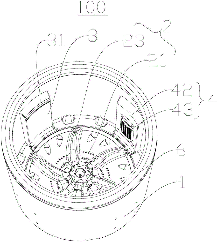
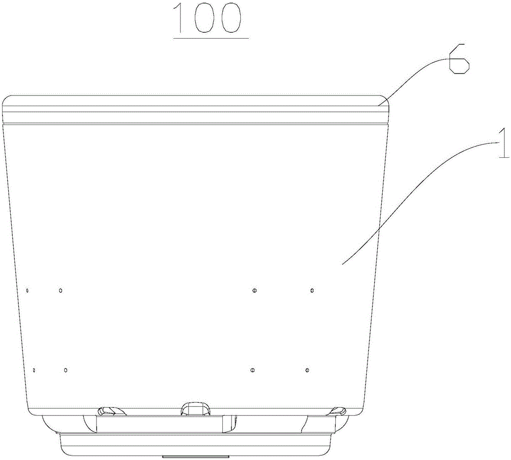
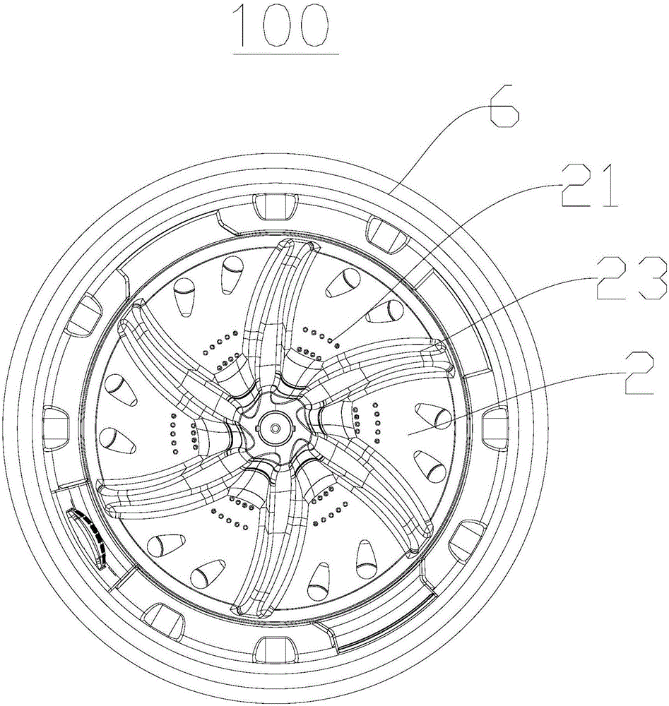

Image

  • Pulsator washing machine
  • Pulsator washing machine
  • Pulsator washing machine

Examples


Embodiment Construction

[0031] Embodiments of the invention are described in detail below, examples of which are illustrated in the accompanying drawings. The embodiments described below by referring to the figures are exemplary and are intended to explain the present invention and should not be construed as limiting the present invention.

[0032] In the description of the present invention, it should be understood that the orientation or positional relationship indicated by the terms "center", "upper", "lower", "top", "bottom", "inner", "circumferential" etc. are based on The orientation or positional relationship shown in the drawings is only for the convenience of describing the present invention and simplifying the description, and does not indicate or imply that the referred device or element must have a specific orientation, be constructed and operated in a specific orientation, and therefore cannot be understood as Limitations on the Invention.

[0033] In addition, the terms "first" and "se...


PUM


Abstract

The invention discloses a pulsator washing machine. The pulsator washing machine comprises a washing bucket, an impeller, a water injection cover plate, a water supply cover plate and a water supply extension part, wherein the impeller is arranged on the inner bottom wall of the washing bucket in a rotating manner, a water accommodating cavity is defined between the impeller and the inner bottom wall of the washing bucket, a through hole is formed in the impeller and is communicated with the water accommodating cavity, and water draining ribs are arranged on the lower surface of the impeller; the water injection cover plate is arranged on the inner peripheral wall of the washing bucket to define a water injection cavity, the bottom of the water injection cavity is communicated with the water accommodating cavity, and a water injection port is formed in the water injection cover plate; the water supply cover plate is arranged on the inner peripheral wall of the washing bucket to define a water supply cavity, and a water supply inlet is formed in the water supply cover plate; the water supply extension part is arranged in the water accommodating cavity to define a water supply channel; and the first end of the water supply channel is communicated with the water supply cavity, and the second end of the water supply channel is positioned in the middle of the water accommodating cavity. The pulsator washing machine can realize a relatively strong water supply function for the water accommodating cavity to ensure large-flow injection water flowing circulation, so that the cleanness of clothes is greatly improved, and washing water amount is reduced.

Description

technical field [0001] The invention relates to the field of household appliances, in particular to a pulsator washing machine. Background technique [0002] In order to solve the problem that the cylinder wall between the inner and outer cylinders is easy to get dirty, the pulsator washing machine of the related art eliminates the outer cylinder, retains the inner cylinder, and designs it as a single cylinder structure that completely seals water except for the top inlet. The current pulsator washing machine of the related art can provide weak washing water flow, which makes the washing time of clothes too long, high energy consumption, and poor washing of clothes. There are two main reasons for the above problems: [0003] 1. Because the pulsator washing machine of the related art only relies on the agitation of the water-repelling ribs when the pulsator rotates to drive the water flow and clothes for washing, and the pulsator itself is limited by the process, and the hei...

Claims


Application Information

Patent Timeline
Patent Type & Authority Applications(China)
IPC IPC(8): D06F17/06D06F17/04D06F39/08
CPCD06F17/04D06F17/06D06F39/088Y02B40/00
Inventor 周鹏邓德喜周福昌
Owner WUXI LITTLE SWAN ELECTRIC CO LTD
Why Eureka
Try Eureka