Assembly type wall and installation method thereof

An installation method and prefabricated technology, applied to walls, building components, buildings, etc., can solve problems such as improper installation, low safety, and unsolid structure, and achieve enhanced solidity, high safety, and reasonable structural design Effect

Active Publication Date: 2017-06-09
河南联力建材科技有限公司
View PDF6 Cites 0 Cited by
  • Summary
  • Abstract
  • Description
  • Claims
  • Application Information

AI Technical Summary

Problems solved by technology

[0003] However, the walls used in this kind of building are made of light-weight materials, and generally only

Method used


Image

  • Assembly type wall and installation method thereof
  • Assembly type wall and installation method thereof
  • Assembly type wall and installation method thereof

Examples


Embodiment 1

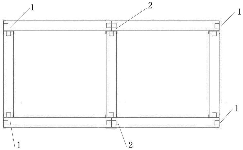
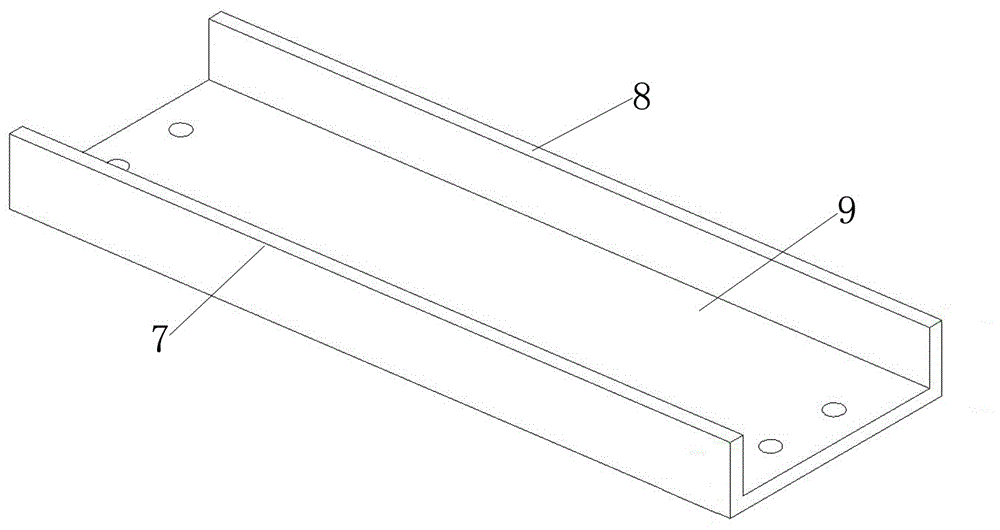
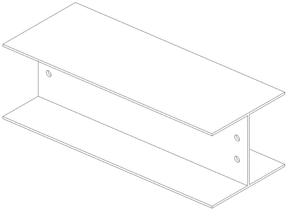
[0024] as attached figure 1 As shown, the installation method of the prefabricated wall includes the following steps: a Fixing columns: Fix four double U-shaped steel structures as columns at the four corners of the room to be installed, and connect the four columns to form a quadrilateral equal to the size of the room , the four double U-shaped steel structures 1 are the main skeleton of the room to be installed, the column is fixed according to the required wall size, the bottom of the column is welded with flat steel, and the flat steel is fastened to the ground through anchor screws, and the fixed column and the foundation The horizontal line of the surface forms 90 degrees; b Connecting beam: U-shaped steel structure is placed on the ground between every two columns as a beam, used to clamp the wall in the beam, and the round hole on the U-shaped steel structure is connected with the screw rod Double U-shaped steel structure 1 The nut holes on the connecting plate are fas...

Embodiment 2

[0027] as attached figure 2 As shown, the installation method of the prefabricated thermal insulation and decoration integrated wall includes the following steps: a Fixing columns: Fix four double U-shaped steel structures 1 as columns at the four corners of the required room, and connect the four columns to form a For a quadrilateral with equal room size, a three-U-shaped steel structure 2 column is installed on the two long sides of the quadrangle formed by the columns. Four double-U-shaped steel structures 1 and two triple-U-shaped steel structures 2 are the main skeleton of the room to be installed. The required wall size is fixed to the column, and the bottom of the column is welded with flat steel, and the flat steel is fastened to the ground through anchor screws, and the fixed column forms a 90-degree angle with the horizontal line of the base; The ground between the two columns is used as a beam, and the round holes on the U-shaped steel structure are respectively fa...


PUM

PropertyMeasurementUnit
Sizeaaaaaaaaaa
Thicknessaaaaaaaaaa

Abstract

The invention provides an assembly type wall. The assembly type wall comprises assembly type wall bodies and installation mechanisms, and the installation mechanisms are used for making the wall bodies connected. Each wall body comprises cement-fiber boards and a heat-insulated board, and the upper and lower sides of each heat-insulated board are bonded with the cement-fiber boards through polyurethane glue. The installation mechanisms of the wall bodies comprise H-shaped steel structures, U-shaped steel structures and double-U-shaped steel structures. An installation method comprises the following steps that firstly, the four double-U-shaped steel structures are fixed to serve as stand columns, the stand columns are fixed according to the required size of the wall, the bottoms of the stand columns are welded with plane steel, and the plane steel is tightly connected with the ground through fang bolts; secondly, one U-shaped steel structure is flat placed on the ground between every two stand columns to serve as a cross beam; thirdly, the wall bodies are embedded in U-shaped cross beam clamping grooves; fourthly, the U-shaped steel structures serving as the cross beams are connected to the tops of the wall bodies in a clamped mode; fifthly, connection seams among the stand columns, the cross beams and the assembly type wall bodies are filled with a silicone weatherproof sealant by means of a gluing device, and a splicing seam of a convex groove and a concave groove between every two wall bodies is filled with the silicone weatherproof sealant by means of the gluing device. The assembly type wall is reasonable in structural design, and the installation method is simple and convenient for construction and installation.

Description

technical field [0001] The invention belongs to the field of assembled walls, and in particular relates to an installation method of an assembled integrated wall with thermal insulation and decoration. Background technique [0002] In recent years, prefabricated buildings have been slowly introduced into the construction of some simple factory buildings or sheds, and prefabricated walls have replaced traditional red brick structures; the mechanized production of workshops has greatly reduced the errors that cannot be avoided by manual operations. The house building mode will prefabricate the frame, wall, roof, etc. in the factory, and then transport it directly to the construction site, and then build and assemble it, which breaks the disadvantages of traditional house construction such as long construction period. [0003] However, the walls used in this kind of building are made of light-weight materials, and generally only 1-2 floors are built. Improper installation metho...

Claims


Application Information

Patent Timeline
IPC IPC(8): E04B2/60
CPCE04B2/60
Inventor 胡向阳邢中福
Owner 河南联力建材科技有限公司
Why Eureka
Try Eureka