Gearbox driving bevel pinion shaft

A technology for bevel gears and gear shafts, applied in gear lubrication/cooling, belts/chains/gears, shafts, etc., can solve problems such as insufficient lubrication, collisions, and failure to shift gears smoothly, and achieve the effect of improving the lubrication effect

Inactive Publication Date: 2017-06-09
CHONGQING KANGTIAN GEAR
View PDF8 Cites 1 Cited by
  • Summary
  • Abstract
  • Description
  • Claims
  • Application Information

AI Technical Summary

Problems solved by technology

Bevel gears are used to change the direction of torque transmission. Although the existing bevel gear shafts can meet the requirements to a certain extent, there are still shortcomings such as insufficient lubrication and jamming and collision when meshing with other tooth structures, resulting in failure to smoothly In addition, the existing secondary bevel gear shaft also has the problem of easy disengagement

Method used


Image

  • Gearbox driving bevel pinion shaft
  • Gearbox driving bevel pinion shaft
  • Gearbox driving bevel pinion shaft

Examples


Embodiment Construction

[0020] The present invention will be further described below in conjunction with the accompanying drawings and specific embodiments, so that those skilled in the art can better understand the present invention and implement it, but the examples given are not intended to limit the present invention.

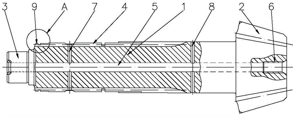
[0021] Such as figure 1 As shown, it is a structural schematic diagram of an embodiment of the driving bevel gear shaft of the gearbox in the present invention. The active bevel gear shaft of the gearbox in this embodiment includes a gear shaft body 1, one end of the gear shaft body 1 is provided with a bevel gear 2, and the other end is provided with a connector 3, and the outer peripheral wall of the gear shaft body 1 is provided with a bevel gear 2 and the external spline 4 between the connector 3. The gear shaft body 1 is provided with a central through hole 5, and the end of the central through hole 5 located on the side of the bevel gear 2 is provided with an internal threa...


PUM


Abstract

The invention discloses a gearbox driving bevel pinion shaft which comprises a pinion shaft body. A bevel gear is arranged at one end of the pinion shaft body, a connecting head is arranged at the other end of the pinion shaft body, and the peripheral wall of the pinion shaft body is provided with an outer spline located between the bevel gear and the connecting head; a center through hole is formed in the pinion shaft body, an internal thread is arranged at the end of the side, where the bevel gear is located, of the center through hole, the inner wall of the center through hole is provided with a radial oil hole I and a radial oil hole II, the radial oil hole I is communicated with the outer spline, and the radial oil hole II is communicated with the position, located between the outer spline and the bevel gear, of the peripheral wall of the pinion shaft body; a meshed tooth section is arranged at the end of the side, close to the connecting head, of the outer spline, all meshed spline teeth of the meshed tooth section are back taper teeth, and the widths of the back taper teeth are gradually decreased in the direction from the connecting head to the bevel gear; and the end faces, facing the connecting head, of the back taper teeth are provided with arc enveloping surfaces formed by arc chamfers.

Description

technical field [0001] The invention belongs to the technical field of gear transmission, and in particular relates to a driving bevel gear shaft of a gearbox. Background technique [0002] The gearbox is composed of gears and shafts. It produces variable speed and torque through different gear combinations. Its functions mainly include: 1. Change the transmission ratio; 2. When the engine rotation direction remains unchanged, the car can run backwards; 3. Use neutral gear , to interrupt the power transmission so that the engine can start, idle, and facilitate the transmission to shift gears or perform power output. Bevel gears are used to change the direction of torque transmission. Although the existing bevel gear shafts can meet the requirements to a certain extent, there are still shortcomings such as insufficient lubrication and jamming and collision when meshing with other tooth structures, resulting in failure to smoothly In addition, the existing slave bevel gear sh...

Claims


Application Information

Patent Timeline
Patent Type & Authority Applications(China)
IPC IPC(8): F16C3/02F16H55/02F16H57/04
CPCF16C3/02F16H55/02F16H57/042
Inventor 肖登强马健
Owner CHONGQING KANGTIAN GEAR
Why Eureka
Try Eureka