Support rack

A technology of support frames and supports, which is applied in the field of support frames and can solve problems such as easy damage to pulleys

Inactive Publication Date: 2017-06-09
STATE GRID CORP OF CHINA +2
View PDF9 Cites 5 Cited by
  • Summary
  • Abstract
  • Description
  • Claims
  • Application Information

AI Technical Summary

Problems solved by technology

[0005] The purpose of the present invention is to provide a support frame to solve the problem in the prior art that the pulleys are easily damaged when the support is heavy

Method used


Image

  • Support rack

Examples


Embodiment Construction

[0018] Embodiments of the present invention will be further described below in conjunction with the accompanying drawings.

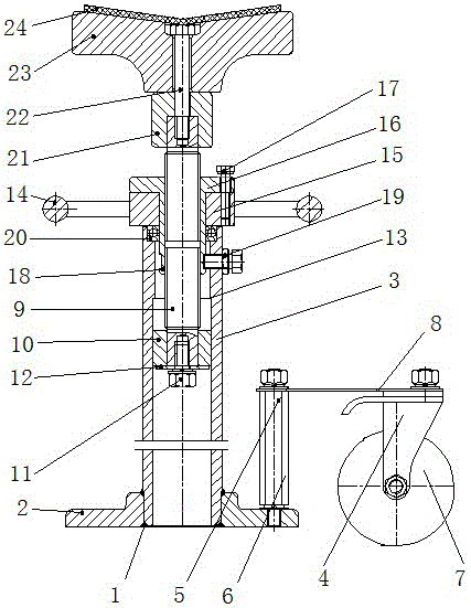
[0019] A specific embodiment of a support frame of the present invention, such as figure 1 As shown, it includes a support base 1, a support member 23, a height adjustment structure arranged between the support base 1 and the support member 23, and a walking wheel 7 arranged on the support base 1 through the wheel frame 4. The wheel frame 4 is provided with a brake plate. The supporting base 1 and the wheel frame 4 are connected by elastic floating support so that the supporting base 1 can float up and down relative to the walking wheels 7, and the supporting base 1 has the ability to float downwards and contact the ground so that it can be jointly supported with the walking wheels 7 to be supported. The support position of the component and the free position off the ground after floating upward. The support base 1 is provided with a screw rod 5 whose ...


PUM


Abstract

The invention relates to a support frame. The support frame includes a support base and a support member arranged on the support base. A walking wheel with a wheel frame is arranged on the support base. The support base is connected to the wheel frame through an elastic floating support. The base has a support position that touches the ground after floating downwards and a free position that breaks away from the ground after floating upwards. When the weight of the piece to be supported is heavy, the supporting base floats down and contacts the ground so that it can support the piece to be supported together with the walking wheels. The role of the road wheel is protected from being crushed. When the weight of the support is light or before the support frame is removed, the support base is in the free position and off the ground. At this time, only the road wheel is used for support.

Description

technical field [0001] The invention relates to a support frame. Background technique [0002] In the power industry, the components of high-voltage switch products generally have more cylindrical shapes. When testing different structural parts, it is necessary to use a support frame to support the outer circle of the cylinder to ensure that the components of high-voltage switch products are the supporting parts and the test device. or other components for accurate and reliable docking. For example, during the docking process of the busbar barrel, the length of the busbar barrel is long and the weight is heavy. The traditional way is to use the crane suspension method to connect the busbar barrel and the insulating basin. However, the crane suspension method not only has high requirements on the site, but also is inconvenient to use due to the limited installation location. . [0003] At present, single-column disc bottom structure or triangular outrigger structure are mos...

Claims


Application Information

Patent Timeline
Patent Type & Authority Applications(China)
IPC IPC(8): F16M11/28
CPCF16M11/28F16M2200/08
Inventor 王春良韩书谟赵玉柱李文杰郝留成田刚领张军民崔文霞李琼可熊保良
Owner STATE GRID CORP OF CHINA
Why Eureka
Try Eureka