
Composite ball core for ball valve

A composite ball and ball valve technology, which is applied in the direction of valve details, valve devices, valve elements and valve seats, etc., can solve the problem that the service life cannot reach the expected goal, it is not perfect, and the local position of the metal substrate is easy to be washed Corrosion and other problems, to avoid liquid corrosion, prolong service life, avoid corrosion effect

Inactive Publication Date: 2015-07-29
YANTAI KINGWAY SCI & TECH
View PDF0 Cites 7 Cited by
  • Summary
  • Abstract
  • Description
  • Claims
  • Application Information

AI Technical Summary

Problems solved by technology

The structure of the current composite ball valve is designed as an asymmetric structure in order to take into account the purpose of strong thermal shock resistance. This structure is not perfect under normal temperature, high-strength erosion, and low-corrosion conditions. Being eroded, the service life cannot reach the expected goal

Method used


Image

  • Composite ball core for ball valve
  • Composite ball core for ball valve
  • Composite ball core for ball valve

Examples


Embodiment 1

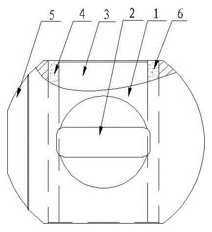
[0025] Embodiment 1, a kind of composite ball core for ball valve, refer to figure 1 , the metal ball core base 1 is provided with a valve stem hole 2 and a flow channel cavity 3, and a ceramic flow channel 4 is fixed in the flow channel cavity 3 close to the cavity wall, and the sealing surface 5 of the metal ball core base 1 is a ceramic sealing surface , which constitutes a structure of the present invention.

Embodiment 2

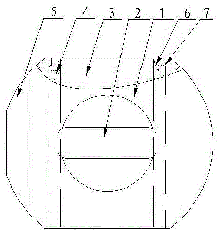
[0026] Embodiment 2, a kind of composite ball core for ball valve, refer to figure 2 On the basis of Embodiment 1, the ceramic flow channel 4 is a ceramic flow channel tube 6, and the ceramic flow channel tube 6 is provided with a shoulder 7 at the end of the fluid outlet direction to prevent the flow channel tube from moving toward the outlet direction, and the others are the same as The embodiments are exactly the same.

Embodiment 3

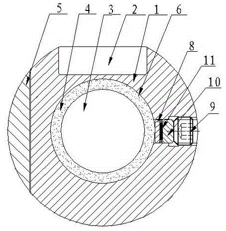
[0027] Embodiment 3, a kind of composite ball core for ball valve, refer to figure 2 , image 3 , on the basis of Embodiment 2, a pressure block 8 is arranged vertically in the metal ball core matrix 1 in the axial direction of the ceramic flow pipe 6, and the compression bolt 9 presses the pressure block 8 to be close to the outer wall of the ceramic flow pipe 6. The pressure block 8 is composed of two pressure pads 10 with a disc spring 11 in the middle, and the others are identical to the embodiment 2.


PUM


Abstract

The invention discloses a composite ball core for a ball valve. The composite ball core is composed of a metal ball core substrate, a valve rod hole and a flow channel cavity and is characterized in that a ceramic flow channel is fixed in the flow channel cavity and close to the cavity wall, and a ceramic sealing surface is used as the sealing surface of the metal ball core. The composite ball core has erosion resistance and pressure resistance when being comparable with a full ceramic ball.

Description

technical field [0001] The invention belongs to the technical field of ball valves, in particular to a composite ball core for ball valves in which structural ceramics are inlaid on a metal ball core, and the flow channel and sealing surface of the ball are made of ceramic materials. Background technique [0002] At present, in the ball valve industry, ceramic ball valves are rapidly seizing the market of metal ball valves due to their incomparable advantages of metal ball valves, such as high wear resistance, high corrosion resistance and high erosion resistance, but large diameter Due to the weak sintering technology of large-scale ceramic products, the ceramic valve has not been successfully developed, so a composite ball valve has emerged. The composite ball valve perfectly combines the advantages of ceramics and metals, creating a ball core with comprehensive performance, which can realize large-diameter ceramics. Mass production of valves. The structure of the current...

Claims


Application Information

Patent Timeline
Patent Type & Authority Applications(China)
IPC IPC(8): F16K5/08F16K25/04
CPCF16K5/08F16K25/04
Inventor 金浩军冯一桀
Owner YANTAI KINGWAY SCI & TECH
Learn More