
Automatic loading and unloading system of copper coil placement equipment

An automatic loading and unloading and placement machine technology, applied in the direction of conveyor objects, transportation and packaging, etc., can solve the poor quality of copper foil placement on the back cover of the mobile phone, the inability to ensure that the back cover of the mobile phone is in a straight state, and the material speed is low low level problem

Active Publication Date: 2017-12-01
FUJIAN SHISHI TONGDA ELECTRICAL APPLIANCE
View PDF8 Cites 7 Cited by
  • Summary
  • Abstract
  • Description
  • Claims
  • Application Information

AI Technical Summary

Problems solved by technology

However, in this copper foil mounting system, the loading and unloading operations of the mobile phone back cover are all manually operated by one or two workers at the loading and unloading station, which results in low loading and unloading speed and high worker intensity. Defects, and manually placing the back cover of the mobile phone cannot ensure that the back cover of the mobile phone is in a straight state, which may easily cause poor quality of copper foil placement on the back cover of the mobile phone

Method used


Image

  • Automatic loading and unloading system of copper coil placement equipment
  • Automatic loading and unloading system of copper coil placement equipment
  • Automatic loading and unloading system of copper coil placement equipment

Examples


Embodiment Construction

[0026] The present invention will be further described below in conjunction with the accompanying drawings and specific embodiments.

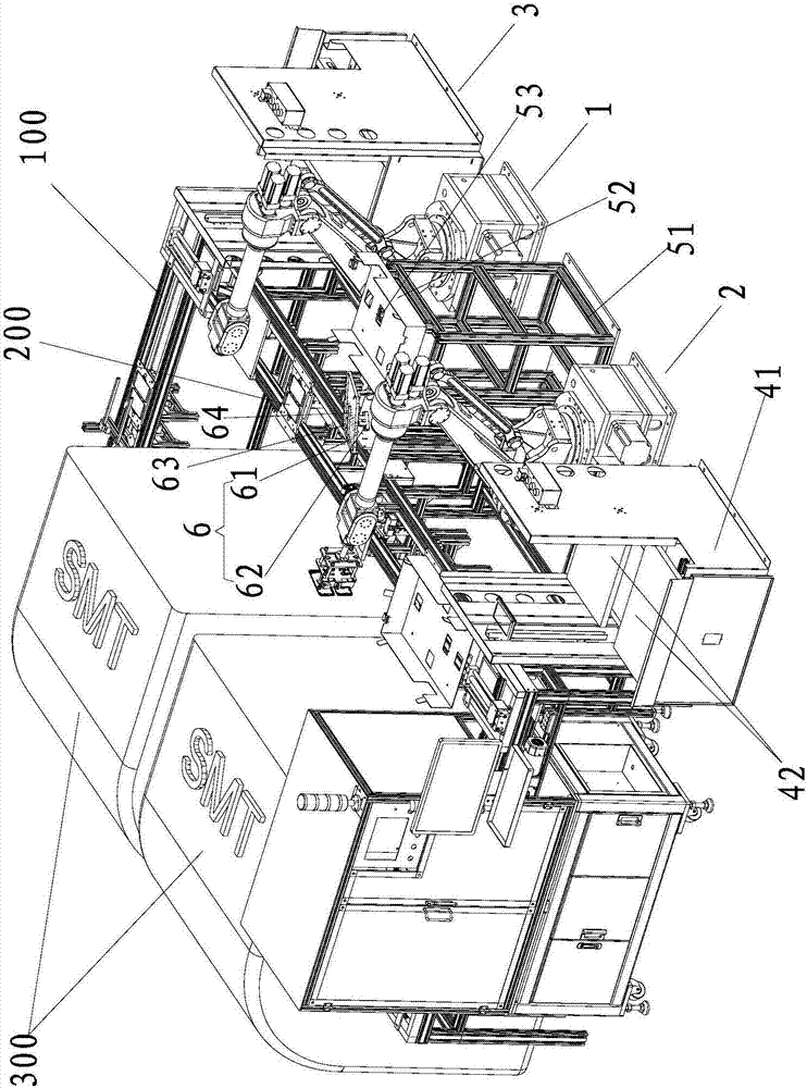
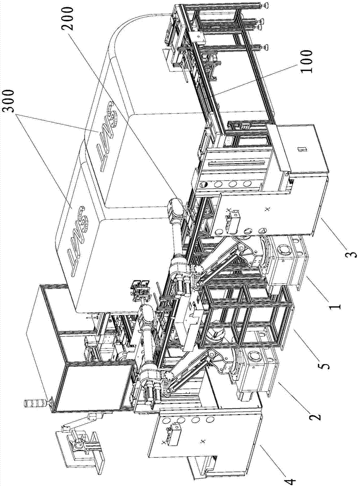
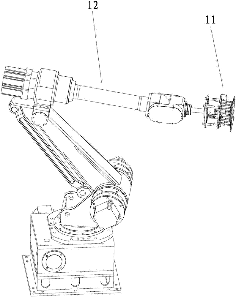
[0027] The automatic loading and unloading system of the copper foil mounting machine of the present invention, such as Figure 1-6 As shown, it includes a closed ring structure, a conveying device 100 for conveying the back cover of the mobile phone and a workpiece tray 200 placed on the conveying device and moving along the circumferential direction of the conveying device 100. The conveying device 100 has a mounting station side and an upper and lower The material station side, that is, the placement station side is the rear side of the conveying device, and the loading and unloading station side is the front side of the conveying device. The placement station side of the conveying device 100 is equipped with a sticker for copper foil placement. Installed 300. In the present invention, the conveying device 100, the workpiece tray 200 and th...


PUM


Abstract

The invention provides an automatic loading and unloading system of copper coil placement equipment. The automatic loading and unloading system comprises a conveying device, a workpiece tray, a loading mechanism, an unloading mechanism, a loading placement device, an unloading placement device, a foam board transfer device and an alignment device, wherein the loading mechanism and the unloading mechanism are used for absorbing and releasing a rear cover of a mobile phone and a foam board; the loading placement device and the unloading placement device are used for placing a stack of foam boards; the foam board transfer device is used for placing one foam board; the alignment device is used for placing the rear cover of the mobile phone, straightening, aligning and correcting the rear cover of the mobile phone; the unloading placement device, the unloading mechanism, the foam board transfer device, the loading mechanism and the loading placement device are positioned in the conveying direction of the loading and unloading station side along the conveying device and are arranged at intervals side by side in sequence; the alignment device and the foam board transfer device are arranged side by side; and the alignment device is positioned between the conveying device and the foam board transfer device. Compared with the prior art, the automatic loading and unloading system has the beneficial effects that the rear cover of the mobile phone is loaded and unloaded in a mechanical automation manner with no need for manual operation; and the automatic loading and unloading system has the advantages of fast loading and unloading speed, low labor intensity of workers, good loading effect and ensuring the placement quality of a copper foil of the rear cover of the mobile phone.

Description

technical field [0001] The invention relates to the field of mobile phone manufacturing, in particular to an automatic loading and unloading system of a copper foil mounting machine for providing copper foil to the back cover of the mobile phone. Background technique [0002] With the development of the economy, the types of products using communication technology are changing with each passing day, especially the use of mobile phones is more popular. The inner surface of the back cover of the existing mobile phone is equipped with a copper foil, which is used to change the radiation direction of the mobile phone antenna, thereby reducing the absorption of the mobile phone's transmission power by the human head, so that the transmission power of the mobile phone can pass through The antenna radiates effectively, thereby significantly improving the radiation efficiency of the mobile phone antenna, making it easier for mobile phone products to pass the OTA project test, and at...

Claims


Application Information

Patent Timeline
Patent Type & Authority Applications(China)
IPC IPC(8): B65G47/91
CPCB65G47/914B65G47/917
Inventor 陈家木陈扬平胡元超
Owner FUJIAN SHISHI TONGDA ELECTRICAL APPLIANCE
Learn More