
Camera module group, structure thereof, and assembly method thereof

A technology of camera module and assembly method, which is applied in the direction of image communication, TV, color TV parts, etc., and can solve the problem that the bonding surface of the lens, mirror holder, and horse lens assembly is difficult to reduce and consumes a lot of time, etc.

Active Publication Date: 2017-06-09
NINGBO SUNNY OPOTECH CO LTD
View PDF10 Cites 16 Cited by
  • Summary
  • Abstract
  • Description
  • Claims
  • Application Information

AI Technical Summary

Problems solved by technology

As camera modules increasingly require high-resolution, large-diameter lenses, the requirement for glue space makes it difficult to reduce the bonding surface of the lens holder and horse lens components. Therefore, the existing structure obviously cannot meet the needs of camera modules needs
[0008] Secondly, since the AA process requires dynamic correction to reserve a wider glue space, it is necessary to apply thicker glue when AA glue is applied than the traditional paste method, which not only increases the production cost, but also increases the amount of glue Difficulty of control
If the amount of glue is too large, the product will have serious glue overflow, which needs to be scraped off later, and the lens will be easily contaminated; if the amount of glue is small, the bonding reliability of the camera module will be poor, and the motor will easily shake or fall off.
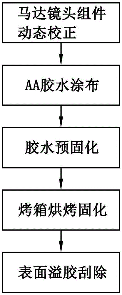
[0009] Third, after the glue coating is completed, two steps of glue pre-curing and oven baking and curing are still required to basically complete the assembly of the camera module, that is, the AA process, which makes the overall process more steps and requires a lot of time. time, and therefore less productive
[0010] Fourth, due to the characteristics of the glue itself, on the one hand, the bonding strength is poor, and it is easy to loosen when subjected to a large external force; on the other hand, it is easily affected by the ambient temperature, and it is easy to deform when the temperature changes. and affect the optical performance of the camera module
[0011] It can be seen from this that for the AA glue assembly method in the prior art, many unfavorable factors have been produced while improving the performance of the camera module through the AA process, which limits the further development of the camera module.

Method used

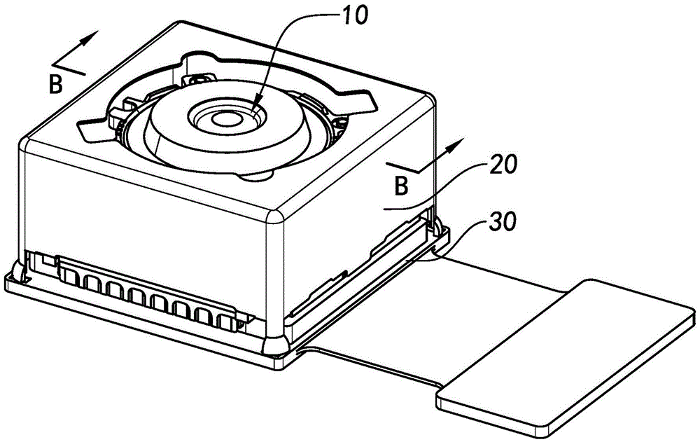

Image

  • Camera module group, structure thereof, and assembly method thereof
  • Camera module group, structure thereof, and assembly method thereof
  • Camera module group, structure thereof, and assembly method thereof

Examples


Embodiment Construction

[0058] The following description serves to disclose the present invention to enable those skilled in the art to carry out the present invention. The preferred embodiments described below are only examples, and those skilled in the art can devise other obvious variations. The basic principles of the present invention defined in the following description can be applied to other embodiments, variations, improvements, equivalents and other technical solutions without departing from the spirit and scope of the present invention.

[0059] The optical performance of the camera module is an important aspect that affects the camera quality of the camera module, and the consistency of the optical axis of the components is the basic factor affecting the optical performance. The AA process is an important way for the camera module to correct the optical axis consistency. However, it can be seen from the foregoing that there are many unfavorable factors in the AA process and the correspond...


PUM


Abstract

The invention discloses a camera module group, a structure thereof, and an assembly method thereof. The camera module group comprises a first motor lens member and a circuit module. The motor lens member is located at a front side of the circuit module, so as to enable the light passing through the motor lens member to reach the circuit module. Moreover, the motor lens member is welded to the circuit module. The assembly method of the camera module group comprises the steps: (A), dynamically adjusting the motor lens member; (B), welding the motor lens member to the circuit module.

Description

technical field [0001] The present invention relates to the field of camera modules, and further relates to a camera module and its structure and assembly method. Background technique [0002] In recent years, with the rapid development of smart phones, the demand for mobile phone cameras is increasing day by day, and the competition of camera modules is becoming increasingly fierce, and the structure and performance of camera modules have been greatly developed. [0003] The basic performance, structure and manufacturing process of the constituent elements of the camera module are important factors for determining the camera parameters of the camera module. Therefore, overall, the improvement of the camera module tends to these three major aspects, and these aspects are interrelated and influenced. [0004] In the existing technology, on the one hand, the basic performance of components, such as manufacturing materials, etc., has been developed to a relatively high level, ...

Claims


Application Information

Patent Timeline
IPC IPC(8): H04N5/225
CPCH04N23/57H04N23/55
Inventor 梅哲文赵波杰王明珠
Owner NINGBO SUNNY OPOTECH CO LTD
Learn More