Exhaust device, pressure cooker cover and pressure cooker

A technology of exhaust device and pressure cooker, applied in pressure cooker, kitchen utensils, home utensils and other directions, can solve problems such as inconvenience of operation, and achieve the effect of simple operation and simple exhaust operation

Active Publication Date: 2019-01-25
GREE ELECTRIC APPLIANCES INC
View PDF3 Cites 43 Cited by
  • Summary
  • Abstract
  • Description
  • Claims
  • Application Information

AI Technical Summary

Problems solved by technology

However, when continuous exhaust is required, the user needs to press the exhaust button all the time, which is extremely inconvenient to operate

Method used


Image

  • Exhaust device, pressure cooker cover and pressure cooker
  • Exhaust device, pressure cooker cover and pressure cooker
  • Exhaust device, pressure cooker cover and pressure cooker

Examples


Embodiment 1

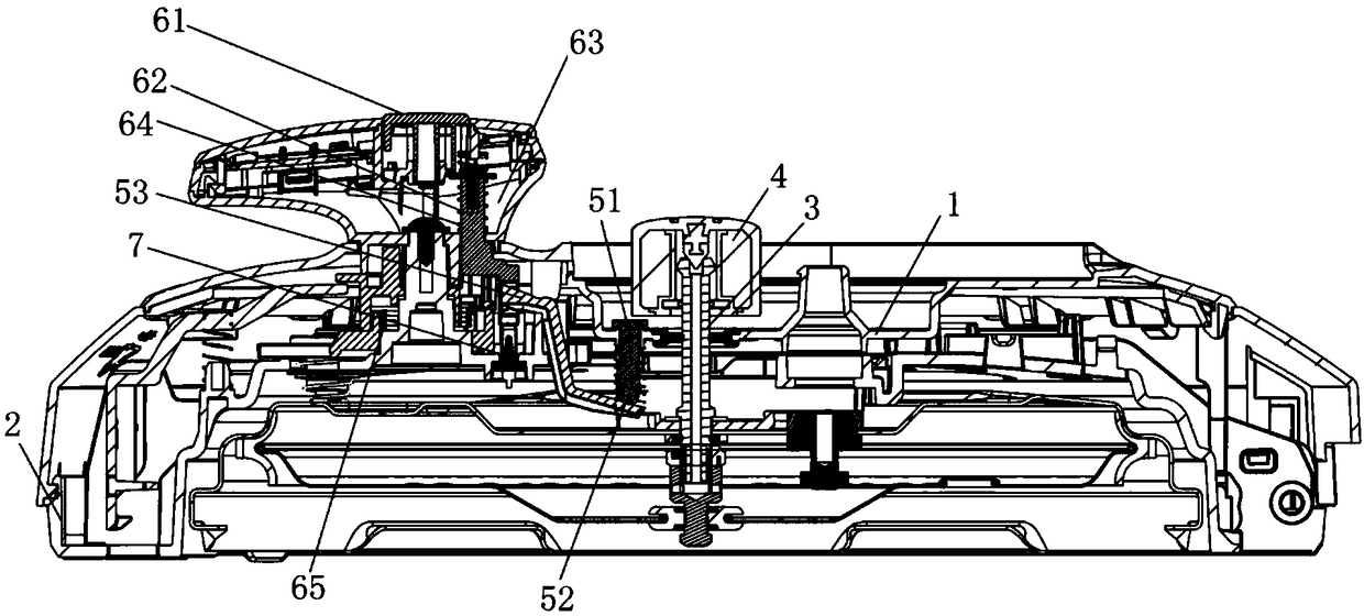
[0068] This embodiment provides an exhaust device, which is used on a pressure cooker; specifically, such as Figure 1 to Figure 11 As shown, the exhaust device in this embodiment includes: a pressure limiting valve 4, a push rod assembly, and a control assembly. Wherein, the pressure limiting valve 4 is fastened on the exhaust pipe 3 of the pressure cooker. The ejector rod assembly is used to jack up the pressure limiting valve 4 to exhaust the exhaust pipe 3 of the pressure cooker. The control assembly is used to control the ejector rod assembly; wherein, the control assembly includes: a control structure, a pressing rod 62 and a limit structure 7 . Wherein, the control structure is arranged on the lid of the pressure cooker. The pressing rod 62 can move to a set position under the control of the control structure, so as to apply a force to the ejector rod assembly, so that the ejector rod assembly pushes up the pressure limiting valve 4 . The limiting structure 7 is arra...

Embodiment 2

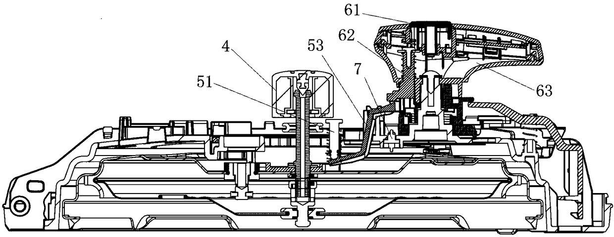
[0071] Preferably, this embodiment provides an exhaust device. Compared with the previous embodiment, the control structure in this embodiment can rotate relative to the cover of the pressure cooker lid; wherein, as Figure 6 and Figure 7 , Figure 10 and Figure 11 As shown, after the exhaust of the pressure cooker is completed, the control structure needs to be rotated to separate the pressing rod 62 from the limit structure 7, so that the pressing rod 62 is far away from the set position. When the ejector rod assembly is not affected by the pressing rod 62, it can Reset, and the pressure limiting valve 4 is fastened on the exhaust pipe of the pressure cooker again.

[0072] In this embodiment, through the above configuration, the user only needs to slightly rotate the control structure to realize the reset of the pressure limiting valve 4 , and the operation is simple.

Embodiment 3

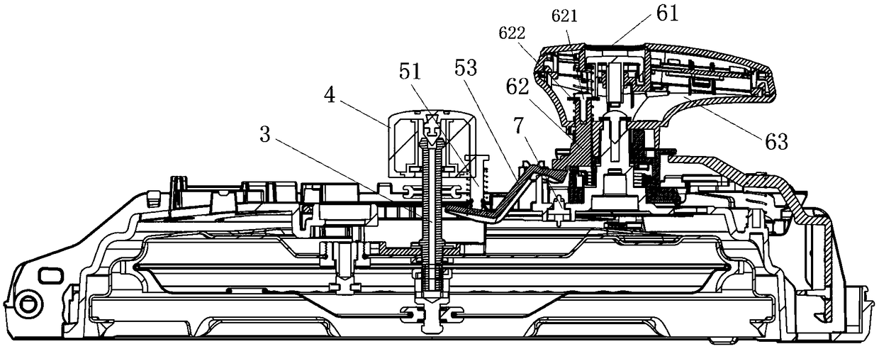
[0074] Preferably, this embodiment provides an exhaust device, compared with the above embodiments, such as Figure 1 to Figure 10 As shown, the control structure in this embodiment includes a pressing member 61 . Wherein, the pressing member 61 is used to press the upper end of the pressing rod 62 to press the pressing rod 62 to a set position. Preferably, the pressing member 61 can be configured as a button, or a button or other structures.

[0075] Preferably, the control structure in this embodiment further includes a handle 63 ; wherein the handle 63 is used to be installed on the lid of the pressure cooker and can rotate relative to the surface cover 1 ; the pressing member 61 is installed on the handle 63 . Preferably, the grip portion of the handle 63 is arranged on the surface cover of the pressure cooker lid, and the lower end of the handle 63 is placed in the pressure cooker lid and connected to the inner lid through a rotating mechanism.

[0076] Preferably, the ...


PUM


Abstract

The invention relates to an air exhausting device, a pressure cooker cover and a pressure cooker, and belongs to the technical field of household appliances. The main technical scheme is that the air exhausting device comprises a relief valve, a jacking rod assembly and a control assembly, wherein the relief valve is buckled on an air exhaust pipe of the pressure cooker; the jacking rod assembly is used to jack up the relief valve; the control assembly comprises a control structure, a pressing rod and a limiting structure; the pressing rod can move to a set position under the control of the control structure to apply acting force to the jacking rod assembly, so that the jacking rod assembly jacks up the relief valve; the limiting structure is arranged on an inner cover of the pressure cooker cover, so as to limit the pressing rod to the set position; when the pressure cooker exhausts air, the control structure controls the pressing rod to move to the set position, and the limiting structure limits the pressing rod to the set position, so that the pressure cooker exhausts air continuously; after air exhausting of the pressure cooker is ended, the control structure controls the pressing rod to get away from the set position, so as to reset the relief valve. The air exhausting device, the pressure cooker cover and the pressure cooker are mainly used for facilitating a user to exhaust air out of the pressure cooker and reset the relief valve.

Description

technical field [0001] The invention relates to the technical field of household appliances, in particular to an exhaust device, a pressure cooker lid and a pressure cooker. Background technique [0002] Electric pressure cooker has become a common electrical appliance in people's daily life. The electric pressure cooker is a more practical cooking appliance. It has the incomparable advantages of other cooking utensils. It can meet various cooking needs, and can quickly, safely and automatically realize various cooking methods. Its energy-saving and nutritious characteristics are very suitable for the needs of modern people. [0003] The existing electric pressure cooker exhausts air mainly by pulling the gravity pressure limiting valve by hand, so that the user is easy to be scalded by the steam. Moreover, the gravity pressure limiting valve has no reset function, and the pressure limiting valve must be manually closed when it is used next time. [0004] In order to prev...

Claims


Application Information

Patent Timeline
Patent Type & Authority Patents(China)
IPC IPC(8): A47J27/08A47J27/09A47J36/38
CPCA47J27/0802A47J27/09A47J36/38
Inventor 麦焕欧阳振华徐奇易庭增张培德张逸鸿
Owner GREE ELECTRIC APPLIANCES INC
Why Eureka
Try Eureka