

Numerical control jig saw
A technology of curve saws and control cabinets, applied in band saws, sawing equipment, wood processing appliances, etc., can solve the problems of inaccurate sawing and low efficiency, and achieve the effect of flexible movement
- Summary
- Abstract
- Description
- Claims
- Application Information
AI Technical Summary
Problems solved by technology
Method used
Image

Examples
Embodiment 1
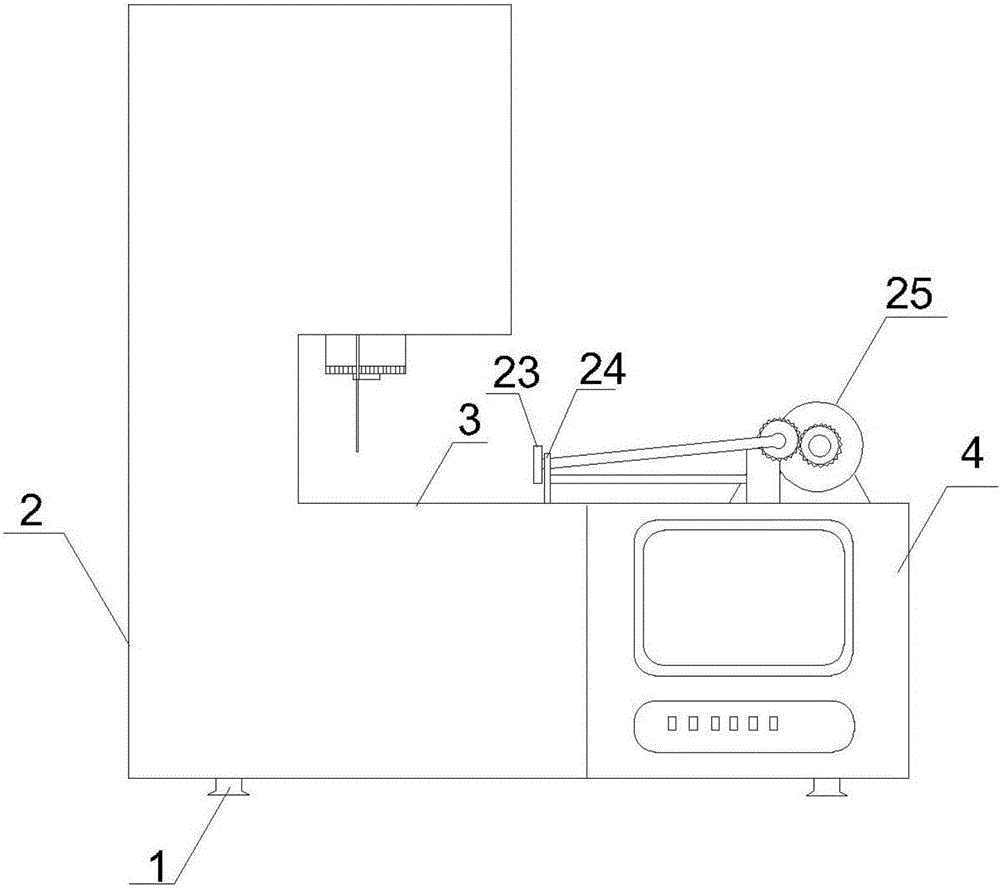
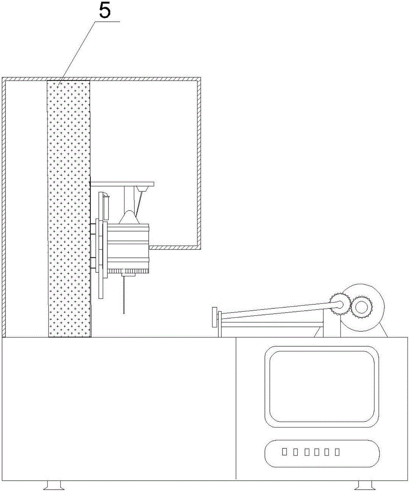
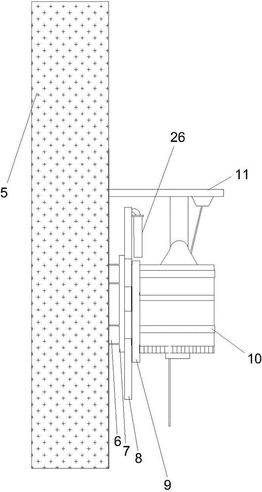
[0033] A numerically controlled jig saw comprising a machine base 1, a frame 2 and a bearing table 3 arranged on the machine base 1, a control cabinet 4 is arranged on the frame, and a jig saw support column 5 is arranged on one side of the frame. One side of the support column 5 is provided with a horizontal sliding rod 6 along the horizontal direction, a connecting plate A7 is sleeved on the horizontal sliding rod, a cylinder and a telescopic rod are provided at one end of the connecting plate A7, and a vertical sliding rod 8 is provided on the connecting plate A7. A connecting plate B9 is sleeved on the vertical sliding rod, and a vertical cylinder 26 is provided on the upper side of the connecting plate B9 to push the connecting plate B9 to slide in the vertical direction. The connecting plate B9 is welded or bolted with a jig saw support ring 10 And auxiliary support plate 11; said support ring 10 is connected with a jig saw steering and driving structure; a section of the ...
Embodiment 2
[0036] A numerically controlled jig saw comprising a machine base 1, a frame 2 and a bearing table 3 arranged on the machine base 1, a control cabinet 4 is arranged on the frame, and a jig saw support column 5 is arranged on one side of the frame. One side of the support column 5 is provided with a horizontal sliding rod 6 along the horizontal direction, a connecting plate A7 is sleeved on the horizontal sliding rod, a cylinder and a telescopic rod are provided at one end of the connecting plate A7, and a vertical sliding rod 8 is provided on the connecting plate A7. A connecting plate B9 is sleeved on the vertical sliding rod, and a vertical cylinder 26 is provided on the upper side of the connecting plate B9 to push the connecting plate B9 to slide in the vertical direction. The connecting plate B9 is welded or bolted with a jig saw support ring 10 And auxiliary support plate 11; said support ring 10 is connected with a jig saw steering and driving structure; a section of the ...
Embodiment 3
[0040] A numerically controlled jig saw comprising a machine base 1, a frame 2 and a bearing table 3 arranged on the machine base 1, a control cabinet 4 is arranged on the frame, and a jig saw support column 5 is arranged on one side of the frame. One side of the support column 5 is provided with a horizontal sliding rod 6 along the horizontal direction, a connecting plate A7 is sleeved on the horizontal sliding rod, a cylinder and a telescopic rod are provided at one end of the connecting plate A7, and a vertical sliding rod 8 is provided on the connecting plate A7. A connecting plate B9 is sleeved on the vertical sliding rod, and a vertical cylinder 26 is provided on the upper side of the connecting plate B9 to push the connecting plate B9 to slide in the vertical direction. The connecting plate B9 is welded or bolted with a jig saw support ring 10 And auxiliary support plate 11; said support ring 10 is connected with a jig saw steering and driving structure; a section of the ...
PUM
 Abstract
Description
Claims
Application Information