
Self-locking type electronic parking brake system in air pressure state

An electronic parking brake, self-locking technology, applied in the direction of brakes, brake components, brake transmission devices, etc., can solve the problems of not easy operation and insufficient safety, shortening the air release time and increasing reliability. and security, the effect of reducing complexity

Pending Publication Date: 2017-06-13
NANJING UNIV OF SCI & TECH
View PDF6 Cites 11 Cited by
  • Summary
  • Abstract
  • Description
  • Claims
  • Application Information

AI Technical Summary

Problems solved by technology

[0006] In a word, the problems in the prior art are: the safety is not high enough, and the operation is not easy enough

Method used


Image

  • Self-locking type electronic parking brake system in air pressure state
  • Self-locking type electronic parking brake system in air pressure state
  • Self-locking type electronic parking brake system in air pressure state

Examples


Embodiment Construction

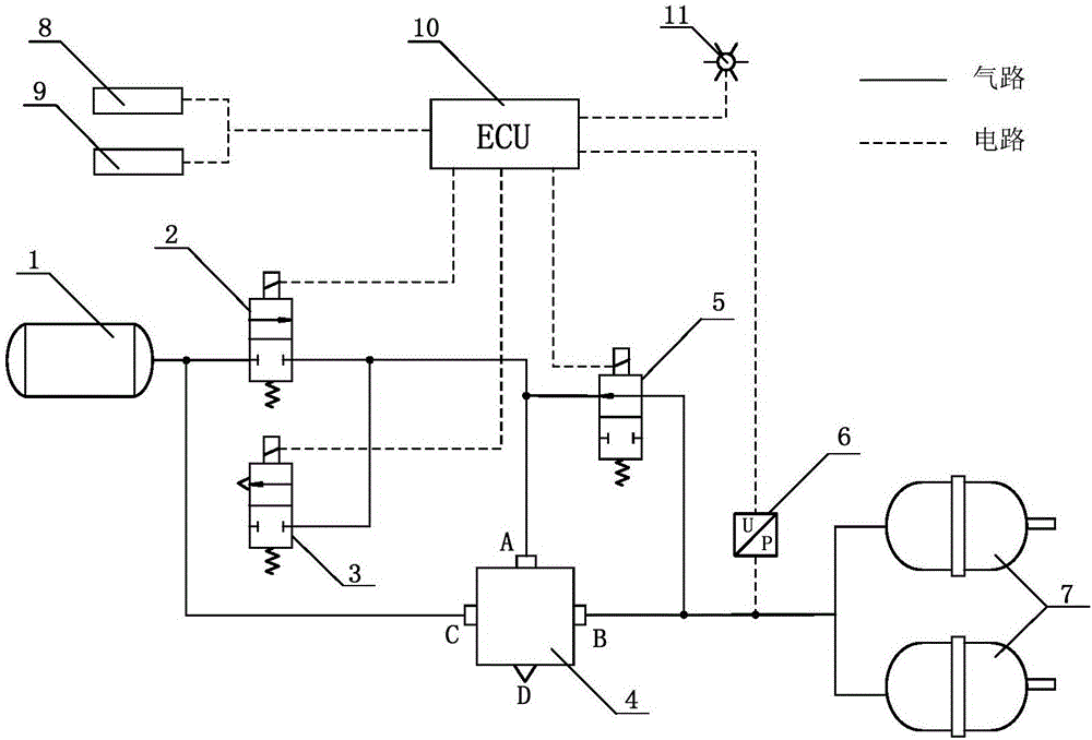
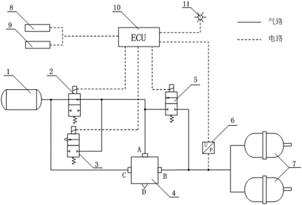
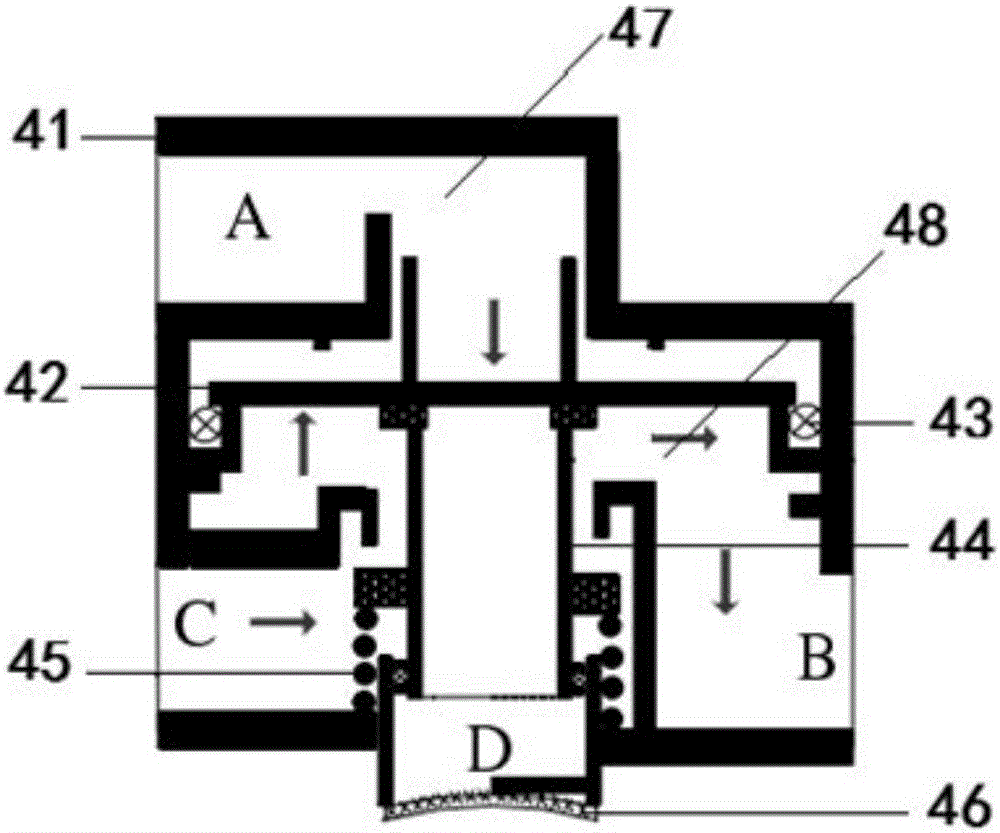
[0021] Such as figure 1 As shown, the air pressure state self-locking electronic parking brake system of the present invention includes an air storage tank 1, a parking brake controller 10, an air pressure sensor 6 and a parking brake chamber 7, and also includes a relay valve 4, The air inlet C of the relay valve 4 is connected to the air storage tank 1, and its air outlet B is connected to the parking brake chamber 7. The input end of the air pressure sensor 6 is connected in series between the relay valve 4 and the parking brake chamber. On the air path between the brake chambers 7, its signal output end is connected with the parking brake controller 10;

[0022] A first solenoid valve 2 is also provided between the control port A of the relay valve 4 and the gas storage tank 1, a third solenoid valve 5 is also provided between the control port A of the relay valve 4 and the gas outlet B, and A second solenoid valve 3 is included, the input end of the second solenoid valve...


PUM


Abstract

The invention discloses a self-locking type electronic parking brake system in an air pressure state. The self-locking type electronic parking brake system in the air pressure state comprises an air storage tank (1), a parking braking controller (10), an air pressure sensor (6), a parking braking air chamber (7), a relay valve (4), a first electromagnetic valve (2), a second electromagnetic valve (3) and a third electromagnetic valve (5), wherein an air inlet (C) of the relay valve (4) is connected with the air storage tank (1) while an air outlet (B) thereof is connected with the parking braking air chamber (7), the input end of the air pressure sensor (6) is serially connected on an air circuit between the relay valve (4) and the parking braking air chamber (7), the first electromagnetic valve (2) is arranged between a control port (A) of the relay valve (4) and the air storage tank (1), the third electromagnetic valve (5) is arranged between the control port (A) of the relay valve (4) and the air outlet (B), and the input end of the second electromagnetic valve (3) is connected with the control port (A) of the relay valve (4). The self-locking type electronic parking brake system in the air pressure state is safe, simple and reliable to operate.

Description

technical field [0001] The invention belongs to the technical field of automobile brake systems, in particular to an air pressure state self-locking electronic parking brake system with simple operation, safety and reliability. Background technique [0002] The electronic parking brake system (EPB) refers to a technology that integrates the temporary braking during driving and the long-term braking after parking, and realizes parking braking by electronic control. At present, the parking brake device of medium and heavy vehicles adopts a pneumatic electronic parking brake device. This kind of parking brake device mostly adopts the principle of "air brake". power. [0003] In order to overcome the disadvantages of insufficient operational safety and poor adaptability of the pneumatic electronic parking brake system of medium and heavy vehicles, a Chinese invention patent application (application number: 201310345261.2, publication date: November 27, 2013) discloses a pneumat...

Claims


Application Information

Patent Timeline
Patent Type & Authority Applications(China)
IPC IPC(8): B60T13/26B60T13/68B60T15/18
CPCB60T13/26B60T13/683B60T15/18
Inventor 王洪亮戴芬王蔚华彭湃刘忠存贾天乐王显会王尔烈皮大伟
Owner NANJING UNIV OF SCI & TECH
Learn More