An automatic unloading tape reel machine

An automatic unloading and coiling machine technology, which is applied in the direction of coiling strips, thin material handling, transportation and packaging, etc. It can solve the problems of affecting the effect of winding, unsuitable for loading and winding, and low feeding efficiency. , to achieve the effect of convenient operation, automatic fast feeding and simple structure

Active Publication Date: 2018-06-22
TONGXIANG YAORUN ELECTRONICS
View PDF6 Cites 0 Cited by
  • Summary
  • Abstract
  • Description
  • Claims
  • Application Information

AI Technical Summary

Problems solved by technology

[0003] Most of the existing carrier tape winding is driven by the winding motor to rotate the winding reel to realize the winding of the material tape. However, most of the existing equipment manually removes the reel from the rewinding shaft. It is time-consuming and labor-intensive. At the same time, it is easy to scatter the rewound loading roll due to excessive pulling force or unbalanced upper and lower forces during the moving process, which affects the rewinding effect. At the same time, the efficiency of unloading is low, so it is not suitable for large-scale Loading and winding

Method used


Image

  • An automatic unloading tape reel machine
  • An automatic unloading tape reel machine
  • An automatic unloading tape reel machine

Examples


Embodiment Construction

[0027] In order to enable those skilled in the art to better understand the technical solution of the present invention, the present invention will be described in detail below in conjunction with the accompanying drawings. The description in this part is only exemplary and explanatory, and should not have any limiting effect on the protection scope of the present invention. .

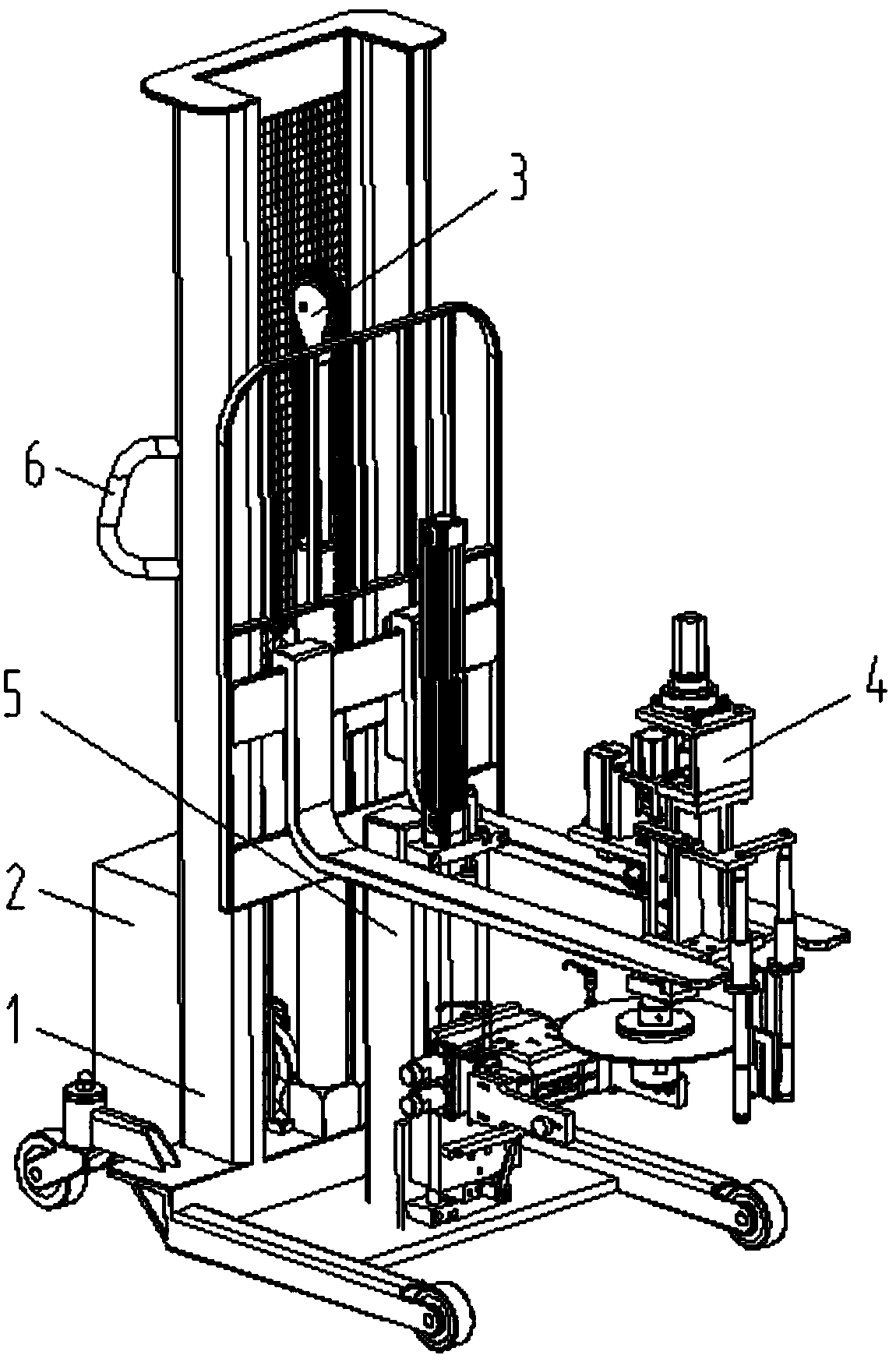
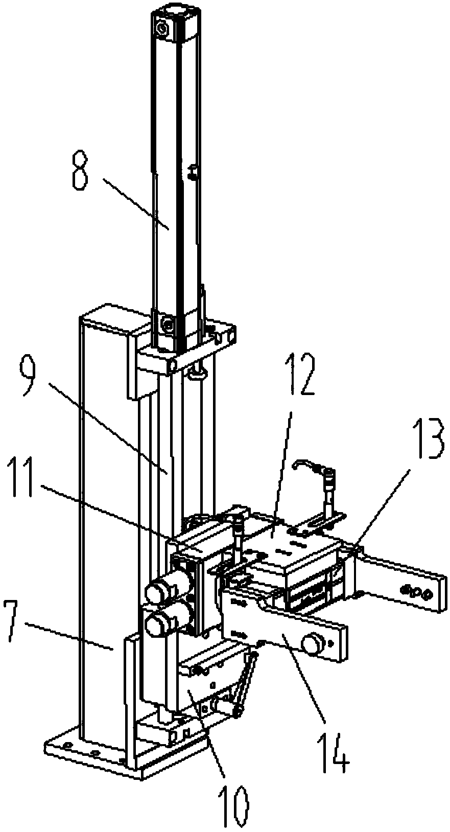
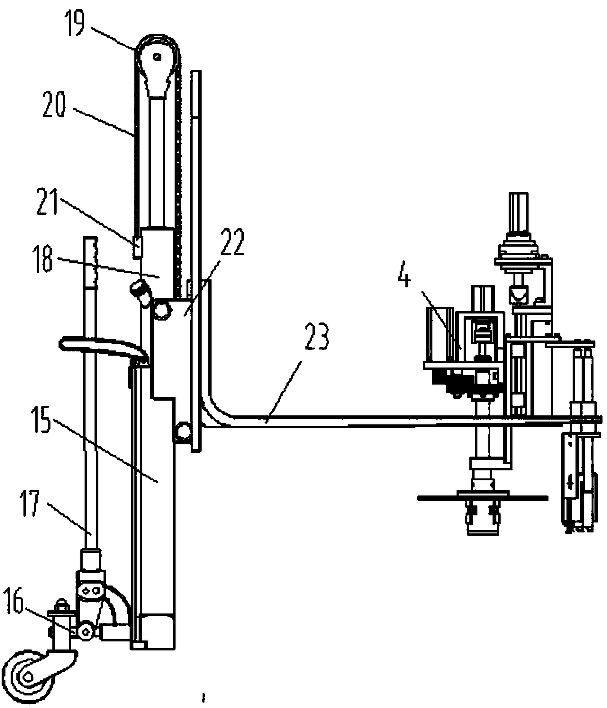
[0028] Such as Figure 1-Figure 4 As shown, the specific structure of the present invention is: a kind of automatic unloading carrier tape reel machine, including frame 1 and power distribution control box 2, described frame 1 is provided with lifting device 3, described The lifting device 3 is provided with a coiling device 4, and the coiling shaft 29 on the coiling device 4 is vertical, and the lower end of the coiling shaft 29 is sleeved with a downward coiling disc 30, and the frame 1 Also be provided with the unloading device 5 that cooperates with coil material tray 30, described unloading devic...


PUM


Abstract

The invention relates to a carrier tape winding machine capable of realizing automatic discharge. The carrier tape winding machine comprises a machine frame and a power distribution control cabinet, wherein a lifting device is arranged on the machine frame; a winding device is arranged on the lifting device; a winding shaft on the winding device vertically runs; a downward winding disc is connected to the lower end of the winding shaft in a sleeving manner; a discharging device matched with the winding disc is also arranged on the machine frame, and comprises a discharge moving device and a discharge clamping device arranged on the discharge moving device; the discharge clamping device is matched with the upper surface and the lower surface of the winding disc with a wound carrier tape; and the lifting device, the winding device, the discharge moving device and the discharge clamping device are connected to the power distribution control cabinet. According to the carrier tape winding machine disclosed by the invention, the winding disc of the winding device is vertically arranged downwards and arranged on the lifting device; and besides, the discharging device is arranged to be matched with the lifting device, the winding disc with the wound carrier tape is vertically clamped by the discharging device, and the lifting device moves in the opposite direction of the lifting device in a matching manner, so that a rapid automatic discharging function can be realized, and besides, the condition that the carrier tape spreads out can be avoided.

Description

technical field [0001] The invention relates to the field of processing equipment for carrier tapes, in particular to a carrier tape coiler capable of automatic unloading. Background technique [0002] With the wide application of various electronic parts and hardware parts, the carrier tape (referred to as the carrier tape) used for the collection of its packaging boxes has also been widely used. Most of the carrier tapes processed by processing equipment are in a spiral shape. In the subsequent use process, the slack loading roll needs to be rewound first, so that it can be wound on the coil reel. [0003] Most of the existing carrier tape winding is driven by the winding motor to rotate the winding reel to realize the winding of the material tape. However, most of the existing equipment manually removes the reel from the rewinding shaft. It is time-consuming and labor-intensive. At the same time, it is easy to scatter the rewound loading roll due to excessive pulling for...

Claims


Application Information

Patent Timeline
Patent Type & Authority Patents(China)
IPC IPC(8): B65H18/10B65H19/30
CPCB65H18/10B65H19/30B65H2701/19
Inventor 邓君徐红娇何楚亮
Owner TONGXIANG YAORUN ELECTRONICS
Why Eureka
Try Eureka