Wire releasing device with replaceable outer sleeve

A technology of pay-off device and jacket is applied in the field of optical fiber pay-off device with replaceable jacket, which can solve the problems of affecting the wiring environment, not being able to shock the reel, and the use environment being harsh, so as to improve the wiring environment, improve the vibration problem, reduce the good shock effect

Active Publication Date: 2017-06-13
陈小娜
View PDF15 Cites 5 Cited by
  • Summary
  • Abstract
  • Description
  • Claims
  • Application Information

AI Technical Summary

Problems solved by technology

At present, in the optical fiber, cable and other industries, passive pay-off devices are being widely used, but most of them have simple structures, insufficient protection, and harsh use environments. Jitter occurs when changing from winding state to straight state, which affects the wiring environment
[0003] In order to solve the problem of optical fiber distribution, in a mechanical damping passive pay-off device disclosed in Patent Document 1, a passive pay-off reel 10 for cable pay-off is provided, but it does not take into account that sometimes the optical fiber will Work in harsh environment, but can't protect the fiber well
[0004] Correspondingly, in order to protect the optical fiber, in the optical fiber winding device disclosed in Patent Document 2, a housing 10 providing optical fiber protection is provided outside the movable winding core 20, but the housing is not universal and cannot be replaced. The problem of affecting the wiring environment due to the jitter generated when the optical fiber is changed from the coiled state to the straightened state is not considered when the optical fiber is arranged in a long-distance, high-altitude, etc.
[0005] In Patent Document 3, a fiber performance testing mechanism is disclosed, and a shock a

Method used


Image

  • Wire releasing device with replaceable outer sleeve
  • Wire releasing device with replaceable outer sleeve
  • Wire releasing device with replaceable outer sleeve

Examples


Embodiment Construction

[0044] Hereinafter, modes for implementing the present invention will be described with reference to the drawings.

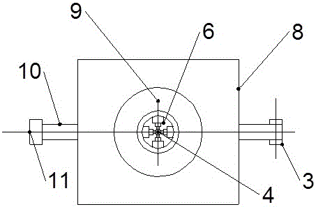
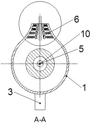
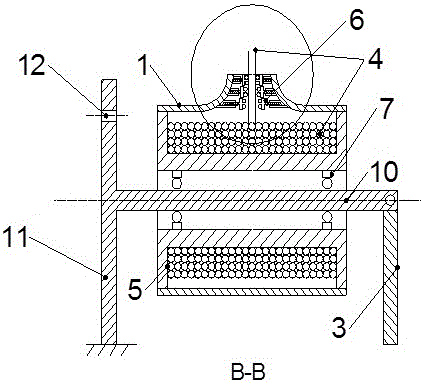
[0045] Figure 1-Figure 7 Be the optical fiber pay-off device of the replaceable jacket of the present invention, as Figure 1-7 As shown, the optical fiber pay-off device with a replaceable jacket of the present invention includes a replaceable jacket 1, a fixed bracket 2, a movable bracket 3, a reel 5 and a guide device 6, and the replaceable jacket 1 is sleeved outside the reel 5, and the connection can be Realized by conventional structures such as threaded connection structure, general buckle structure or nylon structure, the optical fiber 4 is wound up on the reel 5, and one end is fixed on the reel 5, and the other end is arranged outside the pay-off device after passing through the guide device 6, The fixed bracket 2 includes a vertically arranged fixed beam 11 and a horizontally arranged support bar 10. The bottom of the fixed beam 11 is fixed, and is ...


PUM


Abstract

The invention provides a wire releasing device with a replaceable outer sleeve. The replaceable outer sleeve is sheathed on a winding drum and the outer sleeve is provided with an outer bulge; a shock absorber is arranged inside of the outer bulge connected with a pulling rope to carry out combined shock absorption. The wire laying device takes full account of vibration state of the optical fiber and can be well applied to the occasions where the wiring requirements are high. The wire laying device has the advantages of artful structure and low cost.

Description

technical field [0001] The invention relates to a reel pay-off device, in particular to an optical fiber pay-off device with a replaceable jacket. Background technique [0002] In the process of fiber optic cable cutting, due to the large number of fiber cables, it is usually necessary to cooperate with a pay-off device to cut the fiber cables. At present, in the optical fiber, cable and other industries, passive pay-off devices are being widely used, but most of them have simple structures, insufficient protection, and harsh use environments. Jitter occurs when changing from a coiled state to a straightened state, affecting the wiring environment. [0003] In order to solve the problem of optical fiber distribution, in a mechanical damping passive pay-off device disclosed in Patent Document 1, a passive pay-off reel 10 for cable pay-off is provided, but it does not take into account that sometimes the optical fiber will Work in a harsh environment, but can not protect the...

Claims


Application Information

Patent Timeline
IPC IPC(8): B65H49/18B65H75/22B65H57/00
CPCB65H49/18B65H57/00B65H75/22B65H2701/53B65H2701/32
Inventor 陈小娜
Owner 陈小娜
Why Eureka
Try Eureka