
Oil separation and slag removal device

An oil scraping device and oil separation technology, which is applied in the directions of grease/oily substance/float removal device, water/sludge/sewage treatment, liquid separation, etc. Deal with problems such as work difficulties, and achieve the effects of improving oil drainage, thorough oil-water separation, and easy cleaning

Inactive Publication Date: 2017-06-13
JIANGSU ZEYU ENVIRONMENTAL ENG
View PDF4 Cites 3 Cited by
  • Summary
  • Abstract
  • Description
  • Claims
  • Application Information

AI Technical Summary

Problems solved by technology

The solid-liquid separation and oil-water separation of the traditional oil separation and slag removal device are not fine enough, which causes difficulties in the subsequent water treatment work, and the design of the oil discharge structure is relatively cumbersome, resulting in poor oil discharge effect

Method used


Image

  • Oil separation and slag removal device

Examples


Embodiment

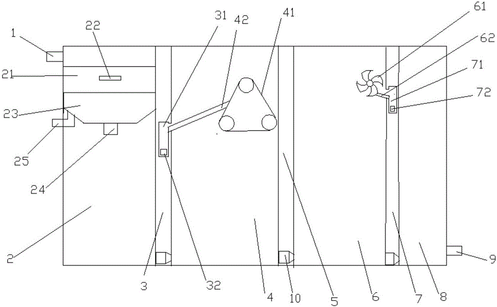
[0019] An oil-separating and slag-removing device, including a box body, the box body is a water inlet 1, a slag-removing area 2, a first partition 3, a first oil-scraping area 4, a second partition 5, The second oil scraping area 6, the third partition 7, the transition area 8 and the water outlet 9,

[0020] The top of the first dividing plate 3, the second dividing plate 5 and the third dividing plate 7 reach the top of the box body, and the bottom end is in close contact with the bottom wall of the box body. The first dividing plate 3, the second dividing plate The bottom ends of the dividing plate 5 and the third dividing plate 7 are all provided with water openings connecting two adjacent areas, and the water openings are provided with water flow deceleration devices 10, and the first dividing plate 3 is provided with a first Oil collecting tank 31, and open towards the first oil scraping area 4 on the upper part of the first oil collecting tank 31, the first oil dischar...


PUM


Abstract

The invention discloses an oil separation and slag removal device which comprises a box body, wherein the box body is sequentially provided with a water inlet, a slag removal region, a first partition, a first oil scraping region, a second partition, a second oil scraping region, a third partition, a transition region and a water outlet from left to right; the slag removal region is provided with a filter frame and a fine filter unit; a first oil collection tank is arranged in the first partition; the first frame is provided with a first oil scraper and an oil scraping plate which communicates the oil scraper with the first oil collection tank; a second oil collection tank is arranged in the third partition; and the inside of the second oil scraping region is provided with a second oil scraper and an oil guide plate which communicates the second oil scraper with the second oil collection tank. The oil separation and slag removal device can implement slag-water separation and oil-water separation more thoroughly, is convenient for oil discharge, and lowers the difficulty of subsequent water treatment.

Description

technical field [0001] The invention belongs to the field of sewage treatment devices, in particular to an oil separation and slag removal device. Background technique [0002] With the vigorous development of the catering industry, the amount of catering oily sewage has also increased sharply, and the random discharge of catering oily sewage will seriously pollute the environment and endanger people's health. The solid-liquid separation and oil-water separation of the traditional oil separation and slag removal device are not fine enough, which causes difficulties in the subsequent water treatment work, and the design of the oil discharge structure is relatively cumbersome, resulting in poor oil discharge effect. Contents of the invention [0003] The invention aims to overcome the deficiencies of the prior art and provide an oil separation and slag removal device. [0004] The technical scheme that the present invention provides for solving the problems of the technolog...

Claims


Application Information

Patent Timeline
Patent Type & Authority Applications(China)
IPC IPC(8): C02F1/40C02F1/00
CPCC02F1/40C02F1/001
Inventor 刘鑫刘灿明延卫毛建军陈金涛祁贵生侯清陈灿龙赵鹤鸣
Owner JIANGSU ZEYU ENVIRONMENTAL ENG
Learn More