Unlock instant, AI-driven research and patent intelligence for your innovation.
A purification device and method for molten salt
What is Al technical title?
Al technical title is built by PatSnap Al team. It summarizes the technical point description of the patent document.
A purification device and molten salt technology, which is applied in the field of molten salt device purification, can solve the problems of polluting electrolytic titanium and increasing the content of titanium oxygen, and achieve the effect of high purification purity and improved purity
Inactive Publication Date: 2019-05-31
宝纳资源控股(集团)有限公司 +1
View PDF7 Cites 0 Cited by
Summary
Abstract
Description
Claims
Application Information
AI Technical Summary
This helps you quickly interpret patents by identifying the three key elements:
Problems solved by technology
Method used
Benefits of technology
Problems solved by technology
Moisture and metal oxides in the electrolyte will contaminate the electrolytic titanium in the molten state, resulting in an increase in the oxygen content of the electrolytic titanium
Method used
Image
Click on the blue label to locate the original text in one second.
Reading with bidirectional positioning of images and text.
Examples
Embodiment 1
[0075] 1. Under airtight conditions, open the vacuum valve of the inert gas / vacuum tube 3 to evacuate until the absolute pressure in the reactor 17 is 50 Pa. After maintaining for 30 minutes, close the vacuum valve of the inert gas / vacuum tube 3 and open the inert gas / vacuum tube 3 Fill the gas valve with argon gas, repeat 2 times, and complete the gas washing.
[0076] 2. Continue to fill with argon until the pressure in the reactor 17 is maintained at a positive pressure of 300 Pa. After heating to 800° C., the NaCl molten salt is introduced into the crucible 16 along the molten salt conduit 2 .
[0077] 3. Connect the cathode compartment 23 and the anode compartment 24 of the electrode compartment 11 to the positive and negative poles of the external power supply through the cathode guide rod 7 and the anode guide rod 9 respectively, feed in a 5A direct current, and perform electrolysis for 4 hours.
[0078] For every 50 minutes of electrification, argon gas was introduced ...
Embodiment 2
[0082] This embodiment is basically the same as Embodiment 1, the difference is:
[0083] 1. The absolute pressure in the reactor 17 is 100 Pa during the scrubbing process, and it is maintained for 40 minutes, and repeated 3 times.
[0084] 2. The molten salt is KCl, and the positive pressure of the molten salt in the reactor 17 is 800 Pa, and the temperature is 750°C.
[0085] 3. The current is 10A DC, and the gas is stirred for 15 minutes every 70 minutes.
[0086] The purified molten salt electrolyte was analyzed for purity, and the purity reached 99.985%, and the oxygen content was 70ppm.
Embodiment 3
[0088] This embodiment is basically the same as Embodiment 1, the difference is:
[0089] 1. The absolute pressure in the reactor 17 is 30 Pa during the scrubbing process, and it is maintained for 30 minutes, and repeated 5 times.
[0090] 2. The molten salt is NaCl-KCl, and the positive pressure of the molten salt in the reactor 17 is 600 Pa, and the temperature is 780°C.
[0091] 3. The current is 7A direct current, and the gas is stirred for 10 minutes every 60 minutes of electricity.
[0092] The purified molten salt electrolyte was analyzed for purity, and the purity reached 99.995%, and the oxygen content was 40ppm.
PUM
Property
Measurement
Unit
thickness
aaaaa
aaaaa
Abstract
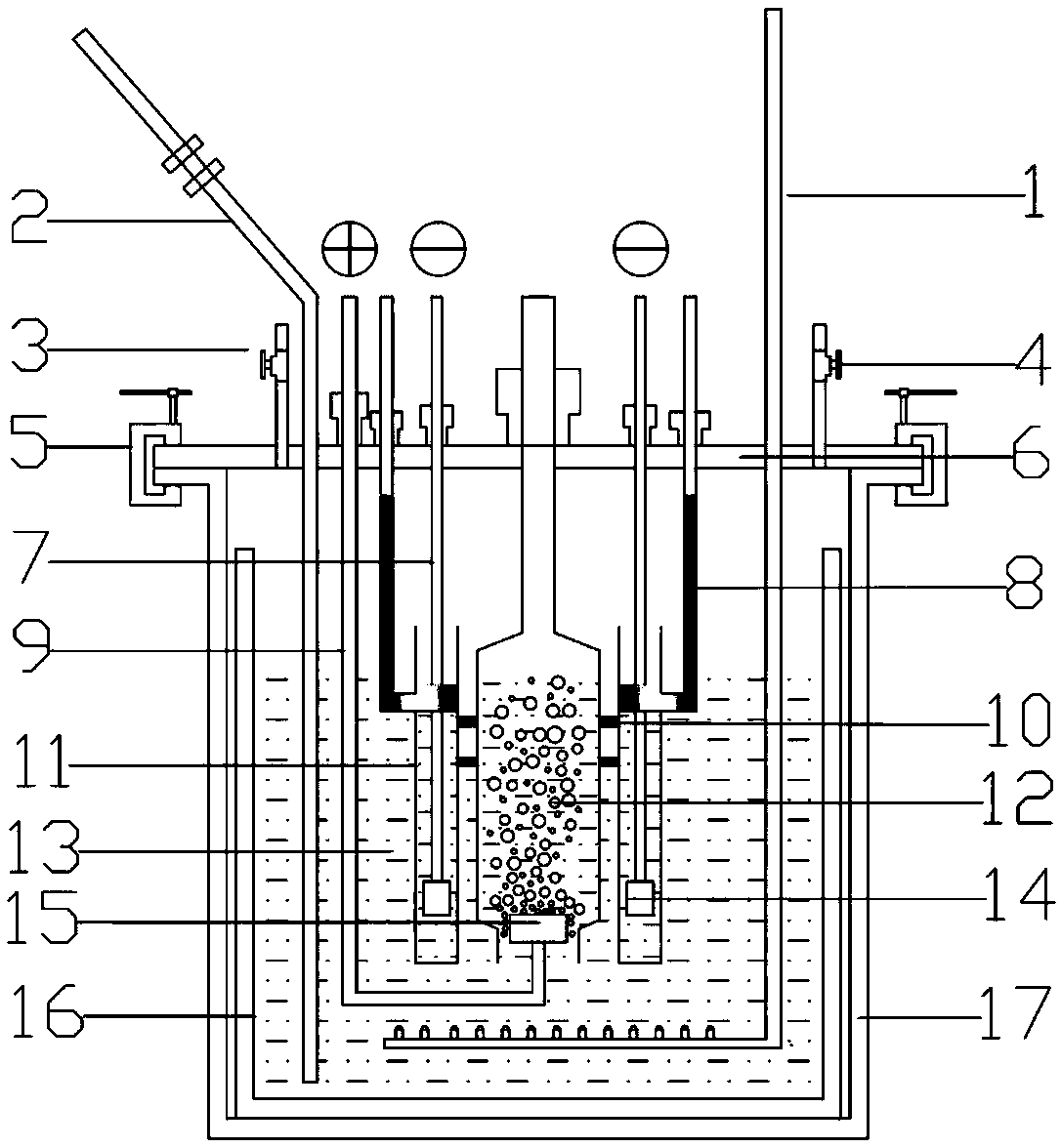
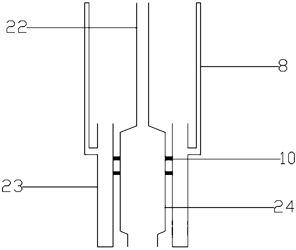
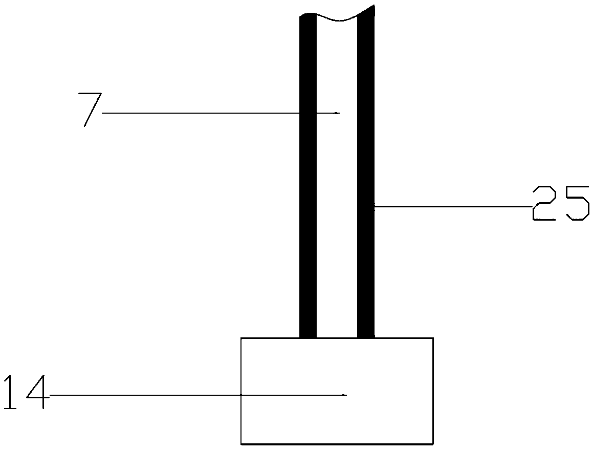
The invention discloses a fused salt purification device and method. The purification device comprises an electrode bin, a reactor with an upper cover, a crucible and an air stirring guide pipe with a spraying nozzle at the lower end; the crucible is arranged in the reactor; the upper cover is connected with a fused salt guide pipe and an inert gas / vacuum pipe; a liquid state metal drainage pipe, a cathode mechanism and an anode mechanism are in sealed connection to the upper cover; the air stirring guide pipe is in sealed connection with the upper cover, and the lower end of the air stirring guide pipe penetrates the upper cover and extends to the lower end of the crucible; the electrode bin comprises an anode gas collecting pipe, a cathode bin and an anode bin; the anode gas collecting pipe is in sealed connection with the upper cover, and the lower end of the anode gas collecting pipe penetrates the upper cover to be communicated with the anode bin; the cathode bin and the anode bin are both arranged in fused salt electrolyte in the crucible, and are fixedly connected through a quartz rod; and the upper end of the cathode bin is communicated with the liquid state metal drainage pipe. By means of the fused salt purification device and method, metal salt and oxide type impurities in fused salt can be effectively removed, the fused salt purification purity is high, continuous production can be achieved, and the purity of electrolysis titanium us effectively improved.
Description
technical field [0001] The invention relates to the technical field of molten salt treatment, in particular to a device purification method for molten salt. Background technique [0002] Among commonly used metals, titanium is one of the most abundant elements in the earth's crust, and its abundance occupies the fourth place among structural metals, second only to aluminum, iron, and magnesium. Titanium is a rare metal material with superior performance. In addition to its superior strength-to-weight ratio, it is suitable for aerospace components. At present, many non-aerospace applications have been developed. It is used in civilian fields such as petroleum, energy, transportation, chemical industry, and biomedicine. It has also been applied to a certain extent, and its application field is still expanding. In recent years, with the rapid development of high-tech fields such as semiconductor technology, information technology, and biomaterials, they have higher and higher ...
Claims
Application Information
Patent Timeline
Application Date:The date an application was filed.
Publication Date:The date a patent or application was officially published.
First Publication Date:The earliest publication date of a patent with the same application number.
Issue Date:Publication date of the patent grant document.
PCT Entry Date:The Entry date of PCT National Phase.
Estimated Expiry Date:The statutory expiry date of a patent right according to the Patent Law, and it is the longest term of protection that the patent right can achieve without the termination of the patent right due to other reasons(Term extension factor has been taken into account ).
Invalid Date:Actual expiry date is based on effective date or publication date of legal transaction data of invalid patent.

