Supercharge Your Innovation With Domain-Expert AI Agents!

High-speed roving traction device

A pulling device and high-speed technology, applied in textiles and papermaking, etc., can solve the problems of not being able to adjust the size and specifications of the roving pulling and winding according to the needs, reducing the efficiency and quality of the roving pulling and winding, and failing to meet the needs of production and use. The effect of strong practicability, improving efficiency and quality, and increasing speed

Inactive Publication Date: 2017-06-13
响水县晨丰纺织有限公司
View PDF11 Cites 0 Cited by
  • Summary
  • Abstract
  • Description
  • Claims
  • Application Information

AI Technical Summary

Problems solved by technology

When the existing roving frame is towed, the reel is generally pre-installed, and the reel needs to be removed after completion, requiring a special expander, which is time-consuming and laborious. In the existing technology, CN201320308253.6 is a pulling device for a roving frame. The traction device of the roving frame includes a circular pie-shaped fixed base plate, a cylindrical connecting shaft tube is provided in the center of the upper surface of the fixed base plate, and a through shaft is provided in the center of the connecting shaft tube. Holes, four drive forks are provided on the circumference of the lower surface of the fixed base plate, and a connecting through hole is respectively provided on the drive forks. Although this patent can solve certain problems in this respect, but There is also a big defect that the size specification of the roving traction and winding cannot be adjusted according to the needs, which reduces the efficiency and quality of the roving traction and winding, and cannot meet the needs of production and use.

Method used


Image

  • High-speed roving traction device
  • High-speed roving traction device
  • High-speed roving traction device

Examples


Embodiment Construction

[0014] The following will clearly and completely describe the technical solutions in the embodiments of the present invention with reference to the accompanying drawings in the embodiments of the present invention. Obviously, the described embodiments are only some, not all, embodiments of the present invention. Based on the embodiments of the present invention, all other embodiments obtained by persons of ordinary skill in the art without making creative efforts belong to the protection scope of the present invention.

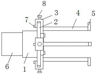
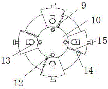
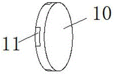
[0015] see Figure 1-3 , the present invention provides a technical solution: a high-speed roving pulling device, including a pulling turntable 1, a connecting shaft 6 is fixedly installed in the middle of one side of the pulling turntable 1, and a fixed shaft is fixedly installed in the middle of one side of the pulling turntable 1 The base plate 2, the middle of one side of the fixed base plate 2 is fixed with an insert plate 10, the periphery of the insert ...


PUM


Abstract

The invention discloses a high-speed roving traction device, which comprises a traction turn table, wherein the middle of one side of the traction turn table is fixedly provided with a connecting shaft barrel; the middle of one side of the traction turn table is fixedly provided with a fixed basal disc; the middle of one side of the fixed base disc is fixedly provided with an insertion disc; the periphery of the insertion disc is provided with jacks; four jacks are arranged; further, every two jacks are distributed at an angle of 90 degrees; certain sides of the jacks are correspondingly provided with first screw holes; first fastening screws are arranged in the first screw holes in a threaded manner; traction blocks are connected into the jacks in an insertion manner; certain ends of the traction blocks are arranged to be in barb shapes and are further connected to the outer side of the fixed basal disc in a clamping manner. A detachable driving fork lever is utilized for the high-speed roving traction device; a user can select a driving fork lever with different lengths according to the demand of wrapping; after the wrapping is completed, the driving fork lever can be directly drawn out; an expander is not used; the high-speed roving traction device is simple and quick, and is convenient to use and high in practicability.

Description

technical field [0001] The invention relates to the technical field of textile machinery equipment, specifically a high-speed roving traction device. Background technique [0002] The roving frame is a spinning machine that makes fiber sliver into roving. Its main function is drafting and twisting, and winding the roving into a certain package to meet the processing requirements of the spinning machine. When the existing roving frame is towed, the reel is generally pre-installed, and the reel needs to be removed after completion, requiring a special expander, which is time-consuming and laborious. In the existing technology, CN201320308253.6 is a pulling device for a roving frame. The traction device of the roving frame includes a circular pie-shaped fixed base plate, a cylindrical connecting shaft tube is provided in the center of the upper surface of the fixed base plate, and a through shaft is provided in the center of the connecting shaft tube. Holes, four drive forks a...

Claims


Application Information

Patent Timeline
IPC IPC(8): D01H13/04
CPCD01H13/04
Inventor 李海建仰波宗清
Owner 响水县晨丰纺织有限公司
Features
  • R&D
  • Intellectual Property
  • Life Sciences
  • Materials
  • Tech Scout
  • Unparalleled Data Quality
  • Higher Quality Content
  • 60% Fewer Hallucinations
Learn More