Construction method for reinforcing steel structure beam or column

A construction method and technology for steel structural beams, applied in truss structures, columns, joists, etc., can solve problems such as torsional bearing capacity that does not involve steel strands, and achieve convenient positioning and connection, restraining twisting, and improving torsional resistance. The effect of carrying capacity

Active Publication Date: 2017-06-13
广东省构建工程建设有限公司
View PDF7 Cites 2 Cited by
  • Summary
  • Abstract
  • Description
  • Claims
  • Application Information

AI Technical Summary

Problems solved by technology

The combination of steel structure + steel strand in the above literature can improve the flexural bearing capacity of the beam, but there is no technical solution on how to improve the torsional bearing capacity of the steel strand in the structure in the prior art

Method used


Image

  • Construction method for reinforcing steel structure beam or column
  • Construction method for reinforcing steel structure beam or column
  • Construction method for reinforcing steel structure beam or column

Examples


Embodiment 1

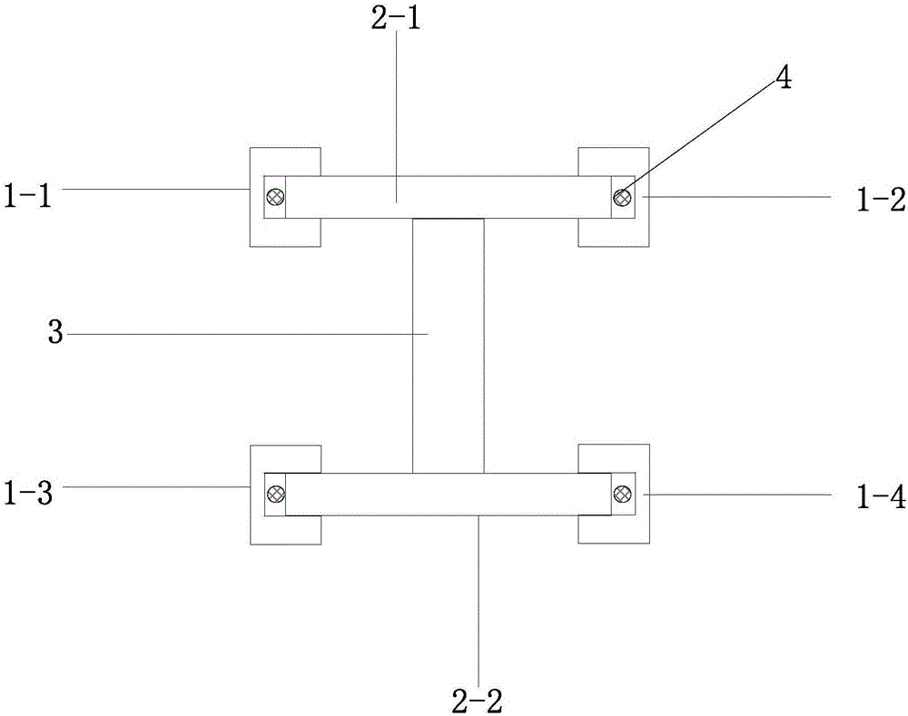
[0020] Embodiment 1: as Figure 1-2 As shown, a construction method for strengthening steel structure side beams, the beam or column adopts basic section steel, and its construction steps are as follows:

[0021] First, prepare components: basic section steel, 4 U-shaped channel steels 1-1, 1-2, 1-3, 1-4; -2. Composed of web 3, the upper flange 2-1 and the lower flange 2-2 have the same structure;

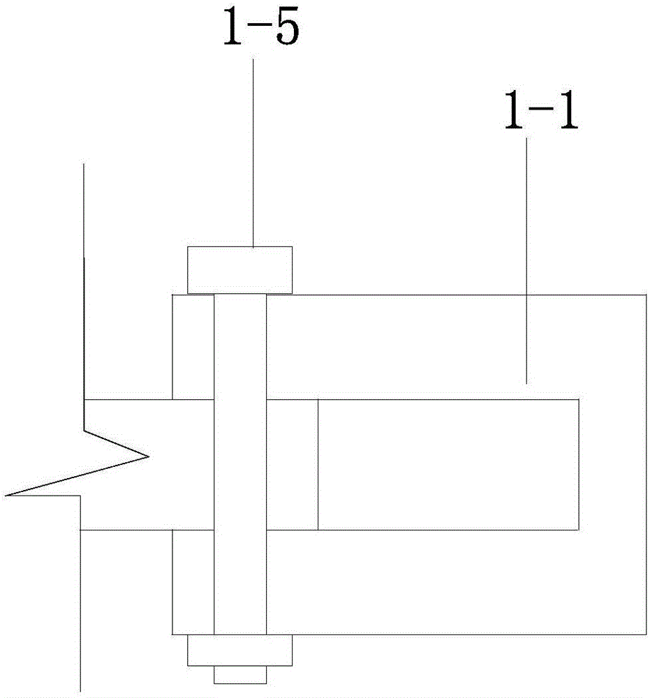
[0022] Second, insert 4 U-shaped channel steels into the four corners of the upper and lower flanges of the foundation steel. Bolt holes are preset between the U-shaped channel steel and the flanges of the foundation steel. The U-shaped channel steel and the foundation The bolt holes of the flange of the section steel are aligned, and the two are fixed by the bolt and nut assembly 1-5; there is a channel 4 through which prestressed tendons are formed between the U-shaped channel steel and the flange;

[0023] Thirdly, the prestressing tendons are passed through the 4-corner tunne...

Embodiment 2

[0024] Embodiment 2: A construction method for strengthening a side column of a steel structure. The difference from Embodiment 1 is that: the base section steel is a column; prestressed steel strands are anchored at the upper and lower ends of the column.

Embodiment 3

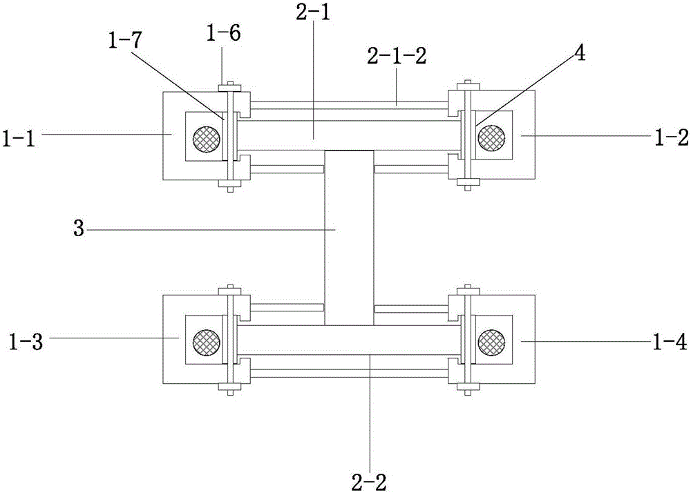
[0025] Embodiment 3: as image 3 Shown, a kind of construction method of reinforcing steel structure beam or column, described beam or column adopts foundation section steel, and its construction steps are as follows:

[0026] First, prepare components: basic section steel, 4 U-shaped channel steels 1-1, 1-2, 1-3, 1-4; -2. Composed of web 3, the upper flange 2-1 and the lower flange 2-2 have the same structure; vertical steel pipes 1-7 are respectively welded on the left and right sides of the upper flange and the lower flange of the basic section steel, and the vertical The flange protrudes toward both ends of the steel pipe, the height of the vertical steel pipe is greater than the thickness of the flange, and the vertical steel pipe is hollow; the distance between the vertical steel pipes is 15-50cm;

[0027] Second, insert 4 U-shaped channel steels into the four corners of the upper and lower flanges of the foundation steel. Bolt holes are preset between the U-shaped chan...


PUM


Abstract

The invention relates to a construction method for reinforcing a steel structure beam or a column. The beam or the column adopts basic shape steel. The construction method comprises the construction steps that firstly, four pieces of U-shaped channel steel are prepared, and the basic shape steel is composed of an upper flange, a lower flange and a web; secondly, the U-shaped channel steel is mounted, specifically, the four pieces of U-shaped channel steel are inserted into four corners of the upper flange and the lower flange correspondingly, arranged along the pass length of the basic shaped steel and fixed to the basic shaped steel, and hole channels for penetrating of prestressing tendons are formed between the U-shaped channel steel and the flanges; and thirdly, the prestressing tendons penetrate through the hole channels of the four corners of the basic shape steel to apply prestress. According to the construction method, the bending/pressing resistant bearing capacity and torsion resistant bearing capacity of the beam/column can be improved simultaneously, and a good effect on improving the torsion resistant bearing capacity of an edge column and an edge beam of a steel structure is achieved.

Description

technical field [0001] The patent of the invention belongs to the field of construction engineering, and specifically relates to a construction method for reinforcing steel structure beams or columns. Background technique [0002] CN105926974 A discloses a steel structure composite beam that increases the load-carrying capacity of the existing steel beam. An auxiliary steel beam is arranged parallel to the lower part of the existing steel beam, and an anchorage and at least one gravitational force are arranged between the existing steel beam and the auxiliary steel beam. Supporting frame, one end of the auxiliary steel beam is fixed, the other end is connected to the force applying device or the auxiliary steel beam is provided with a fastening device, the existing steel beam, auxiliary steel beam and anchor are firmly connected, and it is composed of the fastening device and the gravitational support frame Composite steel beams with increased bearing capacity. The steel st...

Claims


Application Information

Patent Timeline
Patent Type & Authority Applications(China)
IPC IPC(8): E04B1/24
CPCE04B1/24E04B2001/2466E04C3/04E04C3/32E04G21/00E04G23/0218
Inventor 梁亮康忠山谷玉荣高力强李朝红高永强
Owner 广东省构建工程建设有限公司
Why Eureka
Try Eureka