Electric-control slippage lifting platform for building construction

A technology for building construction and lifting platform, which is applied in construction, building structure, housing structure support, etc., can solve problems such as difficulty in meeting the needs of the market construction industry, increasing the labor intensity of construction workers, and high safety hazards for construction workers. Novel, labor-intensive, and high-safety effects

Inactive Publication Date: 2017-06-13
HEFEI ZHIHUI LONGTUTENG INTPROP CO LTD
View PDF1 Cites 20 Cited by
  • Summary
  • Abstract
  • Description
  • Claims
  • Application Information

AI Technical Summary

Benefits of technology

This new technology allows buildings to be built automatically without requiring manual effort or heavy equipment by providing an electronic controlling system that can move along guided tracks instead of traditional methods like cranes. By doing this, they reduce their work load while still being able to maintain stable movement over time. Additionally, these systems have low-shake characteristics making them safer than other types of platforms used at large constructions. Overall, this innovation helps improve efficiency and productivity across various industries such as civil engineering and construction companies' markets.

Problems solved by technology

The technical problem addressed by this patented technology relates to improving the stability and ease-of-use of slideable platforms that are commonly found in architectural constructions such as wall or ceiling designs. These existing systems may cause severe vibrations due to their lack of stable support mechanisms. This makes it challenging for construction staffs who want to work with these tools while still being able to safely carry them around.

Method used


Image

  • Electric-control slippage lifting platform for building construction
  • Electric-control slippage lifting platform for building construction
  • Electric-control slippage lifting platform for building construction

Examples


Embodiment Construction

[0021] The following will clearly and completely describe the technical solutions in the embodiments of the present invention with reference to the accompanying drawings in the embodiments of the present invention. Obviously, the described embodiments are only some, not all, embodiments of the present invention. Based on the embodiments of the present invention, all other embodiments obtained by persons of ordinary skill in the art without making creative efforts belong to the protection scope of the present invention.

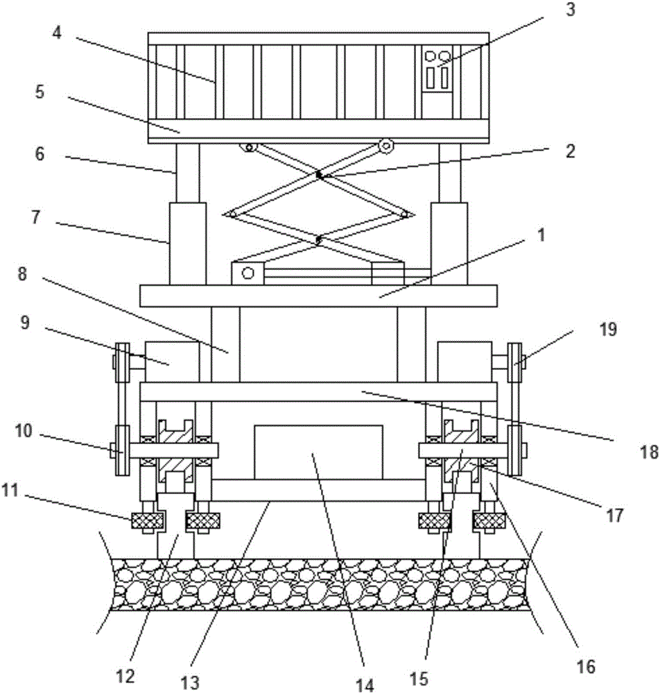
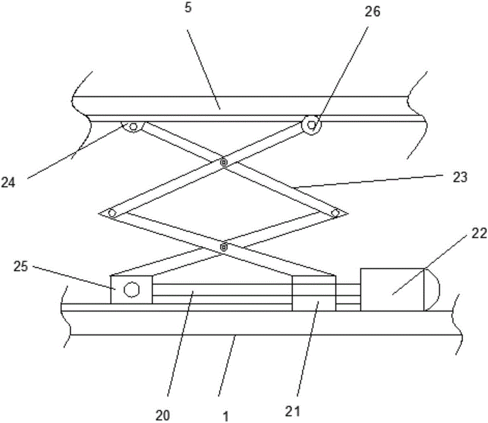
[0022] see Figure 1~3 , in an embodiment of the present invention, an electronically controlled sliding lifting platform for building construction, comprising a support plate 1, a support frame 8 is connected to both sides of the lower end of the support plate 1, and a fixed plate 18 is fixedly connected to the lower end of the support frame 8. Both sides of the upper end of the plate 18 are connected with a driving motor 9, the driving motor 9 is connected w...


PUM


Abstract

The invention discloses an electric control sliding lifting platform for building construction, which comprises a support plate, a support frame is connected to both sides of the lower end of the support plate, a fixed plate is fixedly connected to the lower end of the support frame, a driving motor is connected to both sides of the upper end of the fixed plate, and the driving The motor is connected with a driving wheel, the lower end of the driving wheel is provided with a rotating wheel, the rotating wheel is connected with a rotating shaft, the middle part of the rotating shaft is connected with a slip wheel, the lower end of the fixed plate is fixedly connected with a walking frame on both sides, and the lower end of the walking frame is connected with a balance wheel. There are fixed guide rails between the wheels, reinforced plates are connected between the walking frames, guide sleeves are provided on both sides of the upper end of the support plate, guide posts are provided on the upper end of the guide sleeves, the construction platform is connected to the upper end of the guide posts, and a protective fence is provided on the outside of the construction platform. , the inner side of the construction platform is provided with a control panel, and a lifting device is provided between the lower end of the construction platform and the support plate. The invention realizes the self-controlled mobile walking of the whole construction platform, and satisfies the use requirements of the market and the construction industry.

Description


Claims


Application Information

Patent Timeline
Owner HEFEI ZHIHUI LONGTUTENG INTPROP CO LTD
Why Eureka
Try Eureka