Spliced lamp bar and lamp bar splicing device

A light strip and magnetic device technology, which is applied in the direction of lighting devices, lighting device components, circuit layout, etc., can solve the problems of unsightly appearance, difficulty in adapting to the predetermined installation position, limited application range, etc., and achieve the effect of reducing dark areas

Pending Publication Date: 2017-06-13
GUANGZHOU DONGLIN ELECTRONICS
View PDF4 Cites 6 Cited by
  • Summary
  • Abstract
  • Description
  • Claims
  • Application Information

AI Technical Summary

Problems solved by technology

[0002] As a green, energy-saving solid-state light source, LED lights are more and more widely used in the field of lighting. They are not only suitable for use as lighting in public places, but also can be used as decorative lighting in homes, especially as lighting for some electrical products. And decorative lights, but the current LED lights, because their length is generally fixed, it is difficult to adapt to the predetermined installation position, making the application range very limited
[0003] In view of the above problems, the current LED light strips are solved by splicing, but the splicing of the prior art is connected by external guide wires. After splicing, the overall luminescence is uneven, resulting in dark areas, and it is not beautiful

Method used


Image

  • Spliced lamp bar and lamp bar splicing device
  • Spliced lamp bar and lamp bar splicing device
  • Spliced lamp bar and lamp bar splicing device

Examples


no. 1 example

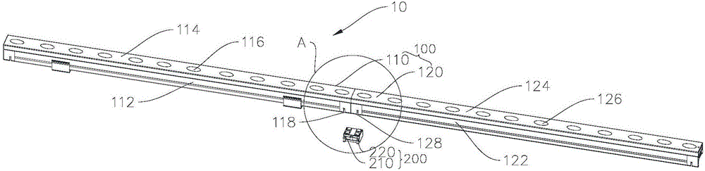
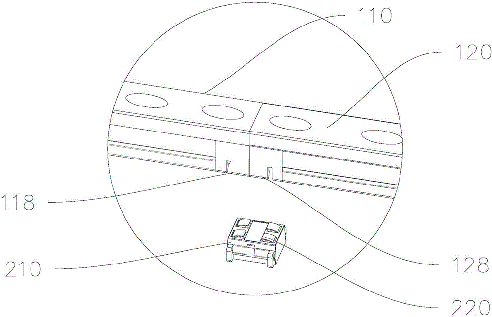
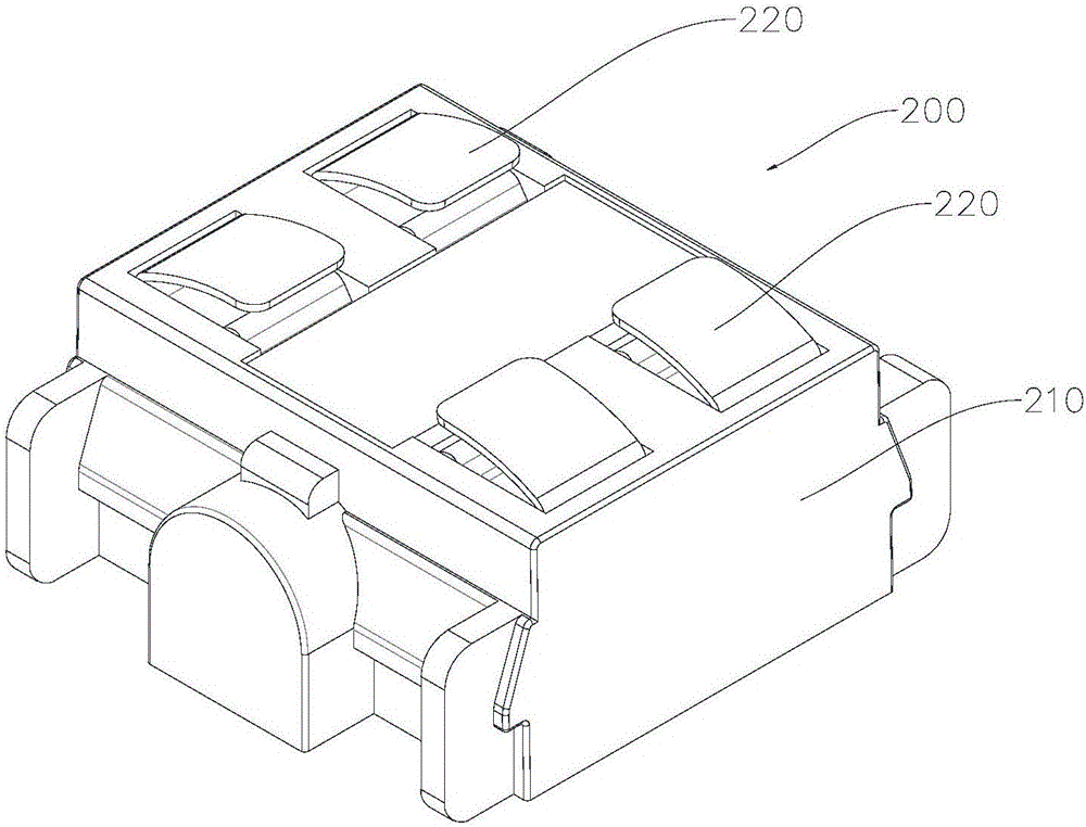
[0034]Please refer to figure 1 and figure 2 , this embodiment provides a splicing light bar 10, which includes a light bar 100 and a splicing component 200, wherein the light bar 100 includes a first light bar 110 and a second light bar 120, and the first light bar 110 and The second light bar 120 is physically connected and electrically connected through the splicing component 200 .

[0035] In this embodiment, the first light bar 110 includes a first housing 112, a first light source board 114, and a plurality of first lamp beads 116. As a method, the first housing 112 is provided with a strip-shaped groove , the groove matches the first light source board 114, and the first light source board 114 is disposed in the groove of the first housing 112, wherein the first light source board 114 is a PCB board. The plurality of first lamp beads 116 are arranged on the first light source board 114. It can be understood that the plurality of first lamp beads 116 are arranged on th...


PUM


Abstract

The invention provides a spliced lamp bar and a lamp bar splicing device and relates to the technical field of lighting equipment. The spliced lamp bar comprises lamp bar bodies and splicing parts; the lamp bar bodies include the first lamp bar body and the second lamp bar body, wherein the first lamp bar body comprises a first shell, a first light source plate arranged in the first shell and a plurality of lamp beads axially arranged along the first light source plate; a first metal conductive piece is arranged at one end of the first light source plate; the second lamp bar body comprises a second shell, a second light source plate arranged in the second shell and a plurality of second lamp beads axially arranged along the second light source plate, and a second metal conductive piece is arranged at one end of the second light source plate; each splicing part comprises a clamping piece and a third metal conductive piece, the clamping pieced is connected with the first shell and the second shell in a clamped manner, the third metal conductive piece is arranged on the clamping piece, and the third metal conductive piece contacts with the first metal conductive piece and the second metal conductive piece respectively. By the arrangement, electric connection and seamless physical connection of the neighboring lamp bars are realized, and the effect of reducing dark areas is achieved.

Description

technical field [0001] The invention relates to the technical field of lighting equipment, in particular to a spliced ​​light bar and a spliced ​​light bar device. Background technique [0002] As a green, energy-saving solid-state light source, LED lights are more and more widely used in the field of lighting. They are not only suitable for use as lighting in public places, but also can be used as decorative lighting in homes, especially as lighting for some electrical products. And decorative lights, but the current LED lights, because their length is generally fixed, it is difficult to adapt to the predetermined installation position, making the application range very limited. [0003] In view of the above problems, the current LED light strips are solved by splicing, but the splicing in the prior art is connected by external guide wires. After splicing, the overall light emission is uneven, resulting in dark areas, and it is not beautiful. Contents of the invention ...

Claims


Application Information

Patent Timeline
Patent Type & Authority Applications(China)
IPC IPC(8): F21S4/20F21V17/10F21V19/00F21V23/06F21Y115/10
CPCF21V17/10F21V19/001F21V23/06
Inventor 王威
Owner GUANGZHOU DONGLIN ELECTRONICS
Why Eureka
Try Eureka