Liquid cooling device for blade server and the blade server

A blade server and liquid cooling technology, applied in the server field, can solve problems such as the inability to exchange heat, and achieve the effect of low environmental requirements

Inactive Publication Date: 2017-06-13
SUGON DATAENERGYBEIJING CO LTD
View PDF4 Cites 5 Cited by
  • Summary
  • Abstract
  • Description
  • Claims
  • Application Information

AI Technical Summary

Problems solved by technology

The external cooling device is cooled by the outdoor unit, and the entire heat exchange process cannot be completed in the cabinet.

Method used


Image

  • Liquid cooling device for blade server and the blade server

Examples


Embodiment Construction

[0020] Embodiments of the present invention will be described in detail below in conjunction with the accompanying drawings.

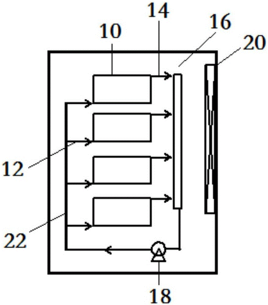
[0021] Such as figure 1 As shown, the present invention provides a liquid cooling device for a blade server, including a box body 10, the box body 10 is used to accommodate blades of the blade server, and the blades are immersed in the refrigerant in the box body 10, wherein, The refrigerant inlet 12 and the refrigerant outlet 14 of the box body 10 communicate with the plate heat exchanger 16 provided in the blade server respectively.

[0022] In the liquid cooling device for the blade server involved in the above embodiments, the refrigerant inlet 12 and the refrigerant outlet 14 are respectively communicated with the plate heat exchanger 16 provided in the blade server, so that the refrigerant can be completed inside the server. Heat exchange, no need to install external heat exchange devices such as outdoor units, energy saving and high efficiency;...


PUM


Abstract

The invention provides a liquid cooling device for a blade server. The device comprises a box for containing a blade of the blade server, and the blade is submerged in a refrigerant in the box, wherein a refrigerant inlet and a refrigerant outlet of the box are separately communicated with a plate heat exchanger arranged in the blade server. The invention further provides the blade server. The liquid cooling device for the blade server and the blade server aim at providing the liquid cooling device for the blade server which is capable of achieving heat exchange in the blade server, and the blade server.

Description

technical field [0001] The present invention relates to the technical field of servers, and more specifically, to a liquid cooling device for a blade server and the blade server. Background technique [0002] Most of the computers currently in use rely on cold air to cool down the machine, but in data centers, air cooling alone is not enough to meet the heat dissipation requirements of high heat flux density servers. The traditional air-cooling mode adopts the indirect contact cooling method. The heat transfer process is complicated, and there are contact thermal resistance and convective heat transfer thermal resistance. The total thermal resistance is large, and the heat transfer efficiency is low. Larger, requires a lower outdoor low-temperature heat source to guide the heat exchange process. [0003] Liquid cooling is to use the working fluid as the intermediate heat transfer medium to transfer the heat from the hot zone to the distant place for cooling. Since the spec...

Claims


Application Information

Patent Timeline
Patent Type & Authority Applications(China)
IPC IPC(8): G06F1/20G06F1/18
CPCG06F1/20G06F1/184G06F2200/201
Inventor 沈卫东王晨吴宏杰李星彭晶楠孙振崔新涛韩磊宋景亮陈进
Owner SUGON DATAENERGYBEIJING CO LTD
Why Eureka
Try Eureka