Method and device for identifying identity through biological imaging and electronic equipment

An image recognition and identity technology, applied in the field of communication, can solve the problem of low reliability, achieve the effect of improving accuracy and reducing the process of identification

Inactive Publication Date: 2017-06-13
武汉仟品网络科技有限公司
6 Cites 4 Cited by

AI-Extracted Technical Summary

Problems solved by technology

[0003] However, with the development of plastic surgery technology, it is becoming easier and easier to obtain an identical face from the perspective of a...

Abstract

The invention provides a method and device for identifying an identity and electronic equipment. The method comprises the following steps that a user image of a to-be-identified character is obtained; a facial region image and a palm region image are extracted from the user image; depth information of the palm region image is obtained, and then a first distance from the palm to a lens is worked out; depth information of the facial region image is obtained, and then a second distance from the face to the lens is worked out; the arm length of a user is worked out according to the first distance and the second distance; when the arm length is located in a prospective region, the facial region image is identified, and then whether the character is a valid user or not is judged. The method and device for identifying the identity and the electronic equipment have the advantage of improving the identification reliability.

Application Domain

Image analysisCharacter and pattern recognition

Technology Topic

Arm lengthsBiological imaging +2

Image

  • Method and device for identifying identity through biological imaging and electronic equipment
  • Method and device for identifying identity through biological imaging and electronic equipment

Examples

  • Experimental program(1)

Example Embodiment

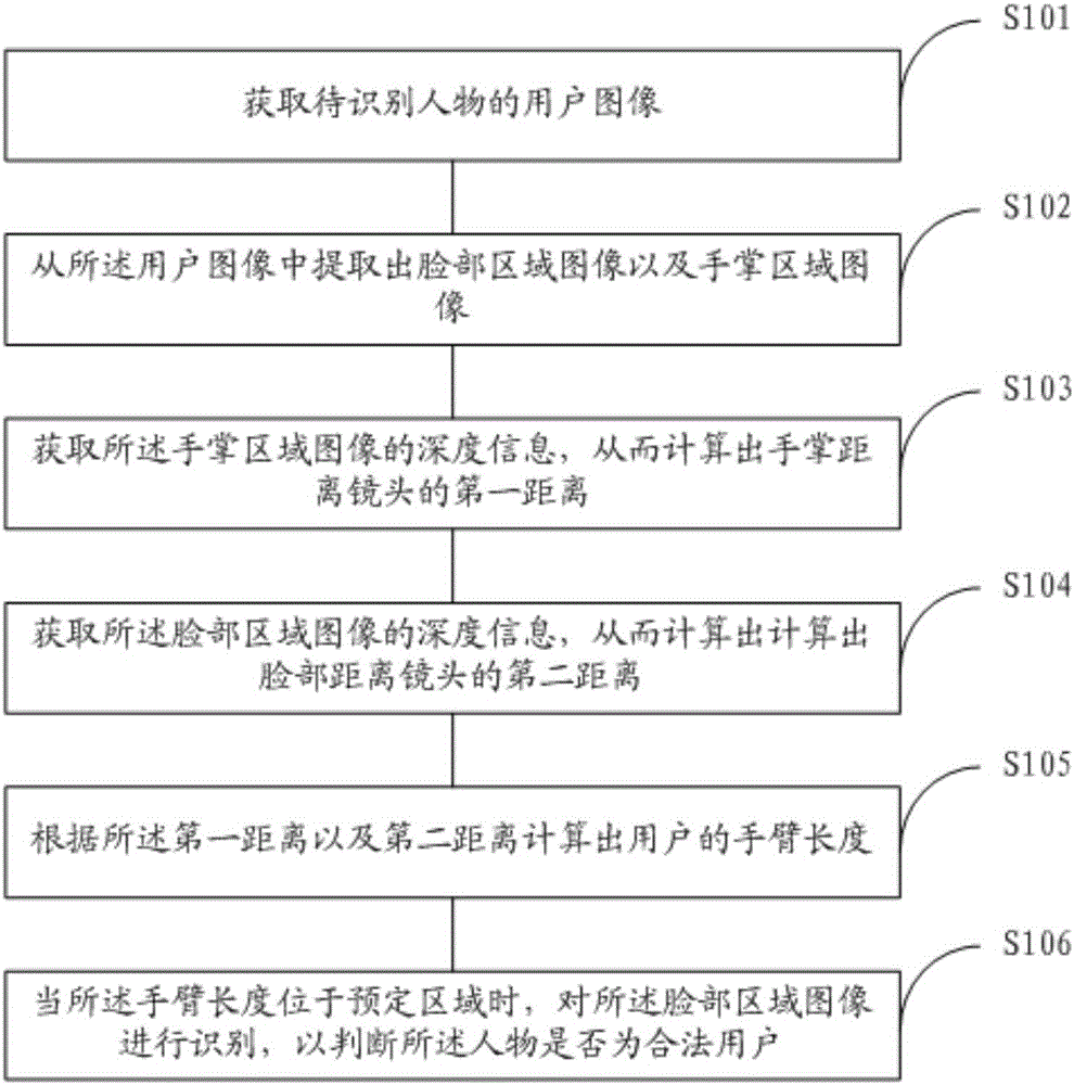
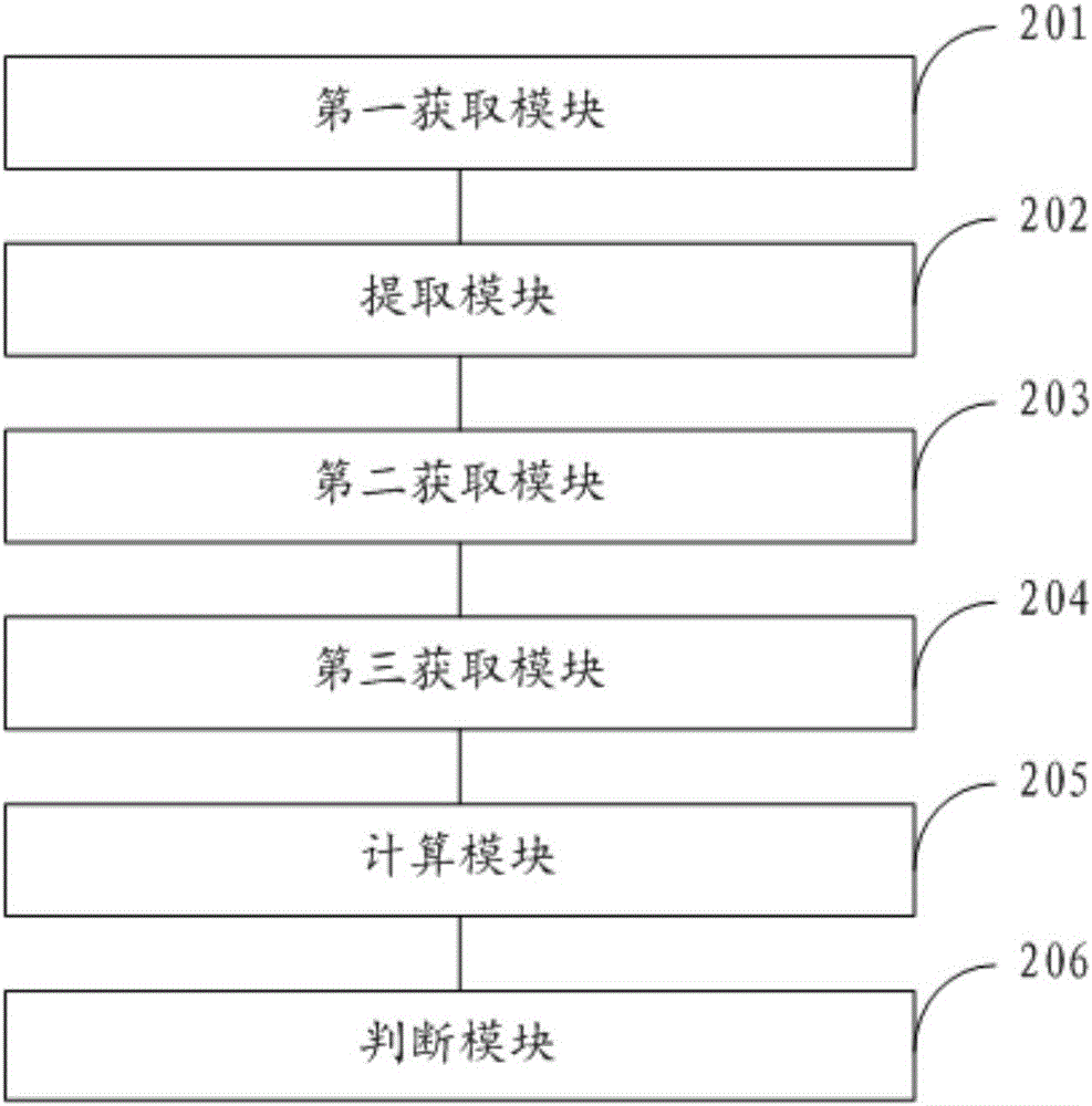
[0048] Referring to the drawings, wherein like reference numerals represent like components, the principles of the present invention are exemplified when implemented in a suitable computing environment. The following description is based on illustrated specific embodiments of the invention, which should not be construed as limiting other specific embodiments of the invention not described in detail herein.
[0049] In the following description, specific embodiments of the present invention are described with reference to steps and symbols for operations performed by one or more computers, unless otherwise stated. Accordingly, it will be appreciated that the steps and operations, which at times are referred to as being performed by a computer, include manipulation by a computer processing unit of electronic signals representing data in a structured form. This manipulation transforms the data or maintains it at a location in the computer's memory system that can reconfigure or otherwise alter the operation of the computer in a manner well known to those skilled in the art. The data structures maintained by the data are physical locations in the memory that have specific characteristics defined by the data format. However, the principles of the present invention are described in the above words, which are not meant to be a limitation. Those skilled in the art will understand that the various steps and operations described below can also be implemented in hardware.
[0050] Please refer to figure 1 , which is a flow chart of a method for identifying an identity through a biometric image, and the method includes the following steps:
[0051] S101. Obtain a user image of a person to be identified;
[0052] S102. Extract a face region image and a palm region image from the user image;
[0053] S103. Obtain the depth information of the palm area image, so as to calculate the first distance between the palm and the lens;
[0054] S104. Obtain the depth information of the face region image, so as to calculate the second distance between the face and the lens;
[0055] S105. Calculate the arm length of the user according to the first distance and the second distance;
[0056] S106. When the arm length is located in a predetermined area, identify the face area image to determine whether the person is a legitimate user.
[0057] Each step of the method for identifying an identity through a biometric image will be described in detail below.
[0058]In this step S101, a user image of a person may be acquired through dual cameras, and Gaussian filter processing, white balance processing, and the like are performed on the user image. Wherein, there is an ordinary camera in the dual camera, which can capture the color image of the person, and the other camera is a depth camera to obtain the depth image of the person, and fuse the color image and the depth image into a color image with depth information. During specific implementation, the person to be recognized must stand within a predetermined range in front of the camera and stretch his arms forward.
[0059] In this step S102, in practical applications, this step S102 includes the following sub-steps:
[0060] S1021. Extract a facial area image from the user image according to the prestored facial contour features;
[0061] The information of the facial contour features of the legal user is pre-stored in the electronic device, and then the facial area image is extracted from the user image according to the facial contour feature information.
[0062] S1022. Extract a palm area image from the user image according to the pre-stored palm outline features.
[0063] The information of the hand contour features of the legal user is pre-stored in the electronic device, and then the hand and face region images are extracted from the user image according to the hand contour feature information.
[0064] In the step S103, the electronic device presets a standard posture with the palm upright and the palm facing the lens. Obtain the depth information of the palm in this posture, and then calculate the first distance corresponding to the depth information according to the existing calculation algorithm, so as to obtain the distance value between the palm and the camera.
[0065] In the step S104, the electronic device presets a standard posture with the person's face facing the camera. Obtain the depth information of the face in the standard posture, and then calculate the distance value corresponding to the depth information according to the existing algorithm. When the distance value is within the predetermined range, use the distance value as the face distance from the lens. Second distance value.
[0066] In practical application, this step S104 includes the following sub-steps:
[0067] S1041. Obtain depth information of the face region image;
[0068] S1042. Calculate the distance value of the face area of ​​the person from the lens according to the depth information;
[0069] S1043. When the distance value is within a predetermined range, use the distance value as a second distance from the face area of ​​the person to the lens;
[0070] S1044. When the distance value is outside the predetermined range, it is determined that acquisition of the second distance between the face area of ​​the person and the camera fails. When acquiring the second distance fails, the user is reminded to reselect a standing position to acquire the user image.
[0071] In this step S105, the arm length can be obtained by subtracting the second distance from the first distance.
[0072] In this step S106, it includes the following sub-steps:
[0073] S1061. When the length of the arm is located in the predetermined area, extract the ear sub-area, nose sub-area, and mouth sub-area in the face area image; since the eyes may blink, in order to avoid multiple recognitions, therefore, do not extract Eye feature information.
[0074] S1062. Extract the ear sub-region, nose sub-region, and mouth sub-region and compare them with the pre-stored ear feature information, nose feature information, and mouth feature information respectively; compare the ear sub-region with the ear feature information, and compare the nose sub-region with the nose feature information The information is compared, and the mouth sub-region is compared with the mouth feature information. Among them, it is mainly to compare the contour feature information and texture feature information of organs.
[0075] S1063. When the difference between the ear sub-region, nose sub-region, and mouth sub-region and the pre-stored ear feature information, nose feature information, and mouth feature information is within a predetermined range, determine that the person is a legitimate user. Since the person will become fatter or thinner, as long as it is within the allowable range of error, it can be determined that the recognition is successful.
[0076] As can be seen from the above, the present invention obtains the user image of the person to be recognized; extracts the face region image and the palm region image from the user image; obtains the depth information of the palm region image, thereby calculating the first distance between the palm and the lens. A distance; obtain the depth information of the face area image, thereby calculating the second distance between the face and the lens; calculate the user's arm length according to the first distance and the second distance; when the arm length When located in a predetermined area, the image of the face area is recognized to determine whether the person is a legitimate user, thereby realizing person recognition. Since it first recognizes the length of the person's arm, and the arm length generally does not change, Then recognize the face, which can not only improve the accuracy of recognition, but also reduce the recognition process when the user is not a legitimate user.
[0077] like figure 2 As shown, the present invention also provides a device for identifying identity through biological images, including:
[0078] The first acquisition module 201 is configured to acquire a user image of a person to be identified;
[0079] An extraction module 202, configured to extract a face area image and a palm area image from the user image;
[0080] The second acquiring module 203 is configured to acquire the depth information of the palm area image, so as to calculate the first distance between the palm and the lens;
[0081] The third acquiring module 204 is configured to acquire the depth information of the face region image, so as to calculate the second distance between the face and the lens;
[0082] A calculation module 205, configured to calculate the user's arm length according to the first distance and the second distance;
[0083] The judging module 206 is configured to recognize the face region image when the arm length is located in a predetermined region, so as to judge whether the person is a legitimate user.
[0084] Wherein, the extraction module 202 includes:
[0085] a first extraction unit, configured to extract a face region image from the user image according to the prestored facial contour features;
[0086] The second extraction unit is configured to extract the palm area image from the user image according to the pre-stored palm outline features.
[0087] The judging module 206 includes:
[0088] The third extraction unit is used to extract the ear sub-region, nose sub-region, and mouth sub-region of the face region image when the arm length is located in a predetermined region;
[0089] A comparison unit, configured to compare the ear sub-region, nose sub-region, and mouth sub-region with prestored ear feature information, nose feature information, and mouth feature information;
[0090] The first judging unit is configured to judge that the character is when the difference between the ear sub-region, the nose sub-region, the mouth sub-region and the pre-stored ear feature information, nose feature information and mouth feature information is within a predetermined range. legitimate user.
[0091] The third acquisition module 204 includes:
[0092] an acquisition unit, configured to acquire depth information of the face region image;
[0093] A calculation unit, configured to calculate the distance value of the face area of ​​the person from the lens according to the depth information;
[0094] A second judging unit, configured to use the distance value as a second distance from the face area of ​​the character to the lens when the distance value is within a predetermined range;
[0095] The third judging unit, when the distance value is outside the predetermined range, judges that acquisition of the second distance between the face area of ​​the person and the lens fails.
[0096] The present invention also provides an electronic device, including the device for identifying an identity through a biological image in the above embodiment.
[0097] Various operations of embodiments are provided herein. In one embodiment, one or more operations described may constitute computer-readable instructions stored on one or more computer-readable media, which, when executed by an electronic device, will cause the computing device to perform the operations described. The order in which some or all operations are described should not be construed to imply that these operations are necessarily order-dependent. Alternative orderings will be appreciated by those skilled in the art with the benefit of this description. Also, it should be understood that not all operations need to be present in every embodiment provided herein.
[0098] Also, the word "preferred" as used herein means serving as an example, instance or illustration. Any aspect or design described herein as "preferred" is not necessarily to be construed as advantageous over other aspects or designs. Rather, use of the word "preferably" is intended to present concepts in a concrete manner. As used in this application, the term "or" is intended to mean an inclusive "or" rather than an exclusive "or". That is, unless otherwise specified or clear from context, "X employs A or B" is meant to naturally include either of the permutations. That is, if X employs A; X employs B; or X employs both A and B, then "X employs A or B" is satisfied in any of the foregoing instances.
[0099] Moreover, while the disclosure has been shown and described with respect to one or more implementations, equivalent alterations and modifications will occur to others skilled in the art upon the reading and understanding of this specification and the annexed drawings. The present disclosure includes all such modifications and variations and is limited only by the scope of the appended claims. With particular regard to the various functions performed by the above-described components (eg, elements, resources, etc.), terminology used to describe such components is intended to correspond to Any component (unless otherwise indicated), even if not structurally equivalent to the disclosed structure that performs the function in the exemplary implementations of the present disclosure shown herein. Furthermore, although a particular feature of the present disclosure has been disclosed with respect to only one of several implementations, such feature may be combined with one or more other implementations as may be desirable and advantageous for a given or particular application. other feature combinations. Moreover, to the extent the terms "comprises", "has", "comprising" or variations thereof are used in the detailed description or the claims, such terms are intended to be encompassed in a manner similar to the term "comprising".
[0100] Each functional unit in the embodiment of the present invention may be integrated into one processing module, or each unit may physically exist separately, or two or more units may be integrated into one module. The above-mentioned integrated modules can be implemented in the form of hardware or in the form of software function modules. If the integrated modules are realized in the form of software function modules and sold or used as independent products, they can also be stored in a computer-readable storage medium. The storage medium mentioned above may be a read-only memory, a magnetic disk or an optical disk, and the like. Each of the above devices or systems may execute the methods in the corresponding method embodiments.
[0101] Embodiments of the present invention have been described above in conjunction with the accompanying drawings, but the present invention is not limited to the above-mentioned specific implementations, and the above-mentioned specific implementations are only illustrative, rather than restrictive, and those of ordinary skill in the art will Under the enlightenment of the present invention, many forms can also be made without departing from the gist of the present invention and the protection scope of the claims, and these all belong to the protection of the present invention.

PUM

no PUM

Description & Claims & Application Information

We can also present the details of the Description, Claims and Application information to help users get a comprehensive understanding of the technical details of the patent, such as background art, summary of invention, brief description of drawings, description of embodiments, and other original content. On the other hand, users can also determine the specific scope of protection of the technology through the list of claims; as well as understand the changes in the life cycle of the technology with the presentation of the patent timeline. Login to view more.

Similar technology patents

Adaptive fault detection method for airplane rotation actuator driving device based on deep learning

InactiveCN104914851Aimprove accuracyReduce the false alarm rate of detection
Owner:BEIHANG UNIV

Video monitoring method and system

Owner:深圳辉锐天眼科技有限公司

Classification and recommendation of technical efficacy words

  • improve accuracy

Golf club head with adjustable vibration-absorbing capacity

InactiveUS20050277485A1improve grip comfortimprove accuracy
Owner:FUSHENG IND CO LTD

Stent delivery system with securement and deployment accuracy

ActiveUS7473271B2improve accuracyreduces occurrence and/or severity
Owner:BOSTON SCI SCIMED INC

Method for improving an HS-DSCH transport format allocation

InactiveUS20060089104A1improve accuracyincrease benefit
Owner:NOKIA SOLUTIONS & NETWORKS OY

Catheter systems

ActiveUS20120059255A1increase selectivityimprove accuracy
Owner:ST JUDE MEDICAL ATRIAL FIBRILLATION DIV

Gaming Machine And Gaming System Using Chips

ActiveUS20090075725A1improve accuracy
Owner:UNIVERSAL ENTERTAINMENT CORP
Why Eureka
Try Eureka