
A method for phase unwrapping in an optical coherence tomography system

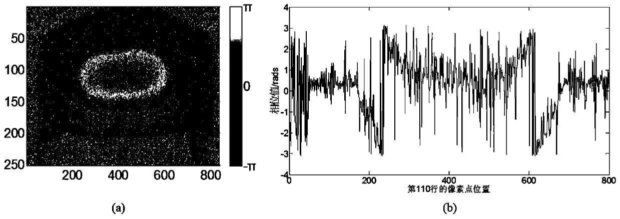
A technology of optical coherence tomography and imaging systems, which is applied in the field of phase unwrapping in optical coherence tomography imaging systems, can solve problems such as discontinuity of phase images, and achieve the effects of low time cost, strong robustness, and weakened noise

Active Publication Date: 2019-07-02
BEIJING INSTITUTE OF TECHNOLOGYGY
View PDF3 Cites 0 Cited by
  • Summary
  • Abstract
  • Description
  • Claims
  • Application Information

AI Technical Summary

Problems solved by technology

[0005] In order to solve the discontinuity problem of the phase image, the present invention provides a method for phase unwrapping in an optical coherence tomography system

Method used


Image

  • A method for phase unwrapping in an optical coherence tomography system
  • A method for phase unwrapping in an optical coherence tomography system
  • A method for phase unwrapping in an optical coherence tomography system

Examples


Embodiment Construction

[0031]The implementation of the method of the present invention will be described in detail below in conjunction with the accompanying drawings.

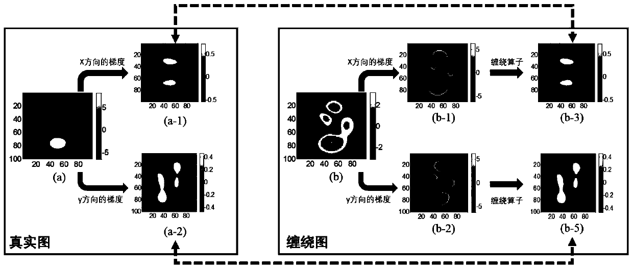
[0032] Since the difference between the wound phase gradient map and the real phase gradient map is that the gradient value of the phase jump boundary is different, the wound phase gradient map is rewound to obtain a restored phase gradient map equivalent to the real phase gradient map. Such as figure 2 as shown, figure 2 (a-1) and figure 2 (a-2) are the true phases respectively figure 2 (a) Two gradient images in x and y directions. Since the real phase map is a continuous image, from a visual point of view, figure 2 (a-1) and figure 2 The values ​​of (a-2) are distributed within a small interval. For the two gradient images of the winding image Fig. 2(b) figure 2 (b-1) and figure 2 (b-2), they have large gradient values ​​at phase jumps. At the corresponding position, these large gradient values ​​have a value of ...


PUM


Abstract

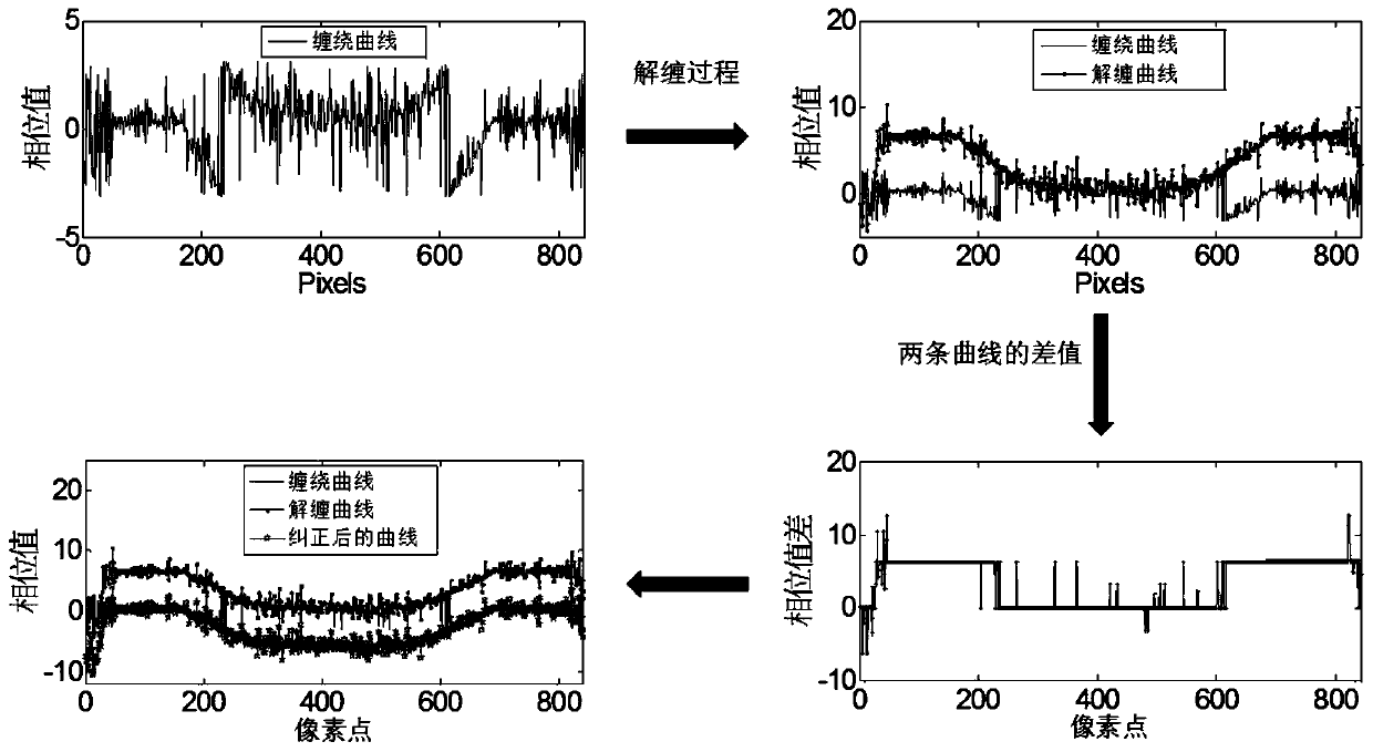
The invention provides a method for phase unwrapping in an optical coherence tomography system. Since the difference between the wrapped phase gradient map and the real phase gradient map is that the gradient value of the phase jump boundary is different, the wrapped phase gradient map is wrapped again to obtain a restored phase gradient map that is equivalent to the real phase gradient map. At the same time, the present invention assumes that the error between the real phase gradient map and the recovered phase gradient map has uncertainty, can take any value, has no constraints, can well solve the phase winding problem in the optical coherent imaging system, and has strong Noise immunity.

Description

technical field [0001] The invention belongs to the technical field of photoelectric imaging, in particular to a method for phase unwrapping in an optical coherence tomography system. Background technique [0002] Precise phase information provides valuable information that can be used in object detection and imaging. So far, phase images have been widely used in interferometric aperture radar, nuclear magnetic resonance imaging, fringe projection profilometry, digital holography, microscopic imaging, and optical coherence tomography. Optical coherence tomography is widely used in biomedical imaging because of its high resolution and real-time three-dimensional imaging. However, for fluid studies of various vascular imaging, the phase map is entangled due to the measurement length exceeding one wavelength, so it is necessary to resolve the phase discontinuity. [0003] In order to solve the phase winding problem, various methods have been proposed in the past, and these me...

Claims


Application Information

Patent Timeline
Patent Type & Authority Patents(China)
IPC IPC(8): G06T11/00G06T5/50G06T5/00
CPCG06T5/50G06T11/008G06T2207/30101G06T2207/10101G06T5/00
Inventor 黄勇夏绍燕谭小地
Owner BEIJING INSTITUTE OF TECHNOLOGYGY
Learn More