
Display device and gate drive circuit and unit

A gate drive and circuit technology, which is applied in the fields of display devices, gate drive circuits and drive units, can solve the problems of large space occupied by wiring, complex wiring of cascade circuits of gate drive units, and complex cascade relationships, etc., to achieve The effect of simple wiring, saving wiring space, and simple cascading relationship

Active Publication Date: 2017-06-13
BOE TECH GRP CO LTD +1
View PDF7 Cites 21 Cited by
  • Summary
  • Abstract
  • Description
  • Claims
  • Application Information

AI Technical Summary

Problems solved by technology

In this way, the entire gate drive circuit uses more gate drive units and occupies a larger area, which is not conducive to the miniaturization and low cost of the display panel.
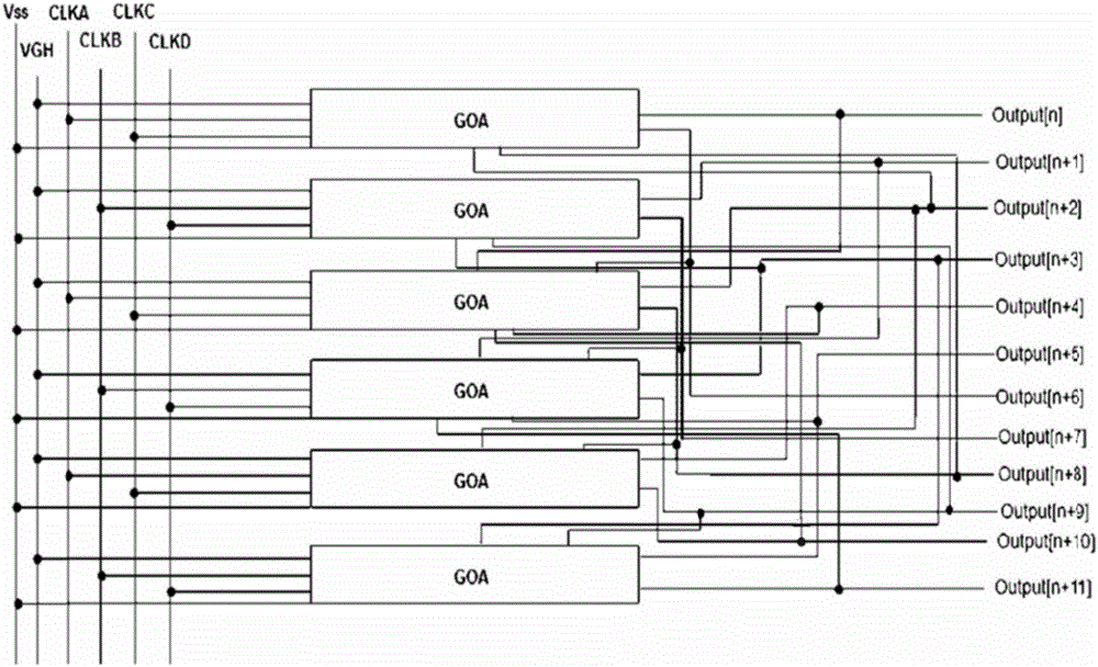
[0004] Although the patent with publication number CN 103474040 discloses a gate drive unit, which can trigger two shift register signals through one trigger signal, reducing the number of gate drive units used in the display device, but the gate drive The cascade circuit layout of the cells is very complex: from figure 1 It can be seen that although the nth gate drive unit (GOA unit) can output two gate drive signals, Output[n] and Output[n+6], the gate drive unit also needs to be output by other GOA units. The gate drive signals Output[n+8] and Output[n+2] are used as input reset signals, resulting in a very complicated cascade relationship, complex wiring and more space. Therefore, the entire gate based on this gate drive unit Due to the need for more cascade wiring space, the pole drive circuit still needs to occupy a large area, which is not conducive to the miniaturization of the display device.

Method used


Image

  • Display device and gate drive circuit and unit
  • Display device and gate drive circuit and unit
  • Display device and gate drive circuit and unit

Examples


Embodiment Construction

[0040] In order to make the object, technical solution and advantages of the present invention clearer, the present invention will be described in further detail below in conjunction with specific embodiments and with reference to the accompanying drawings.

[0041]Embodiments of the present invention are described in detail below, examples of which are shown in the drawings, wherein the same or similar reference numerals designate the same or similar elements or elements having the same or similar functions throughout. The embodiments described below by referring to the figures are exemplary only for explaining the present invention and should not be construed as limiting the present invention.

[0042] Those skilled in the art will understand that unless otherwise stated, the singular forms "a", "an", "said" and "the" used herein may also include plural forms. The expression "and / or" used herein includes all or any elements and all combinations of one or more associated list...


PUM


Abstract

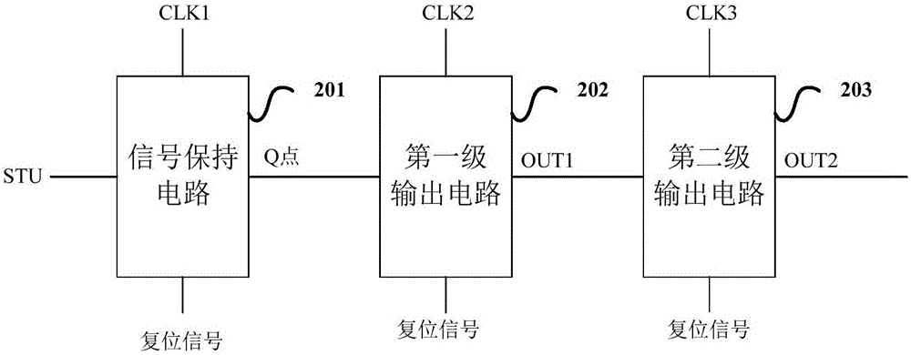
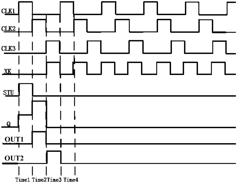
The invention discloses a display device and a gate drive circuit and unit. The gate drive unit comprises a signal holding circuit, a first-level output circuit and a second-level output circuit, wherein the signal holding circuit is used for outputting a high electrical level according to an input high-electrical-level trigger signal during the high-electrical-level period of a first clock signal; the first-level output circuit is used for outputting a high-electrical-level first-stage driving signal according to the high electrical level at the output end of the signal holding circuit during the high-electrical-level period of a second clock signal; the second-level output circuit is used for outputting a high-electrical-level second-stage driving signal according to the high electrical level at the output end of the first-level output circuit during the high-electrical-level period of a third clock signal. The number of gate drive units in the display device is reduced, the cascade relation of the gate drive units can also be simplified, cascade wiring space is saved, and miniaturization and low cost of the display device are benefited.

Description

technical field [0001] The present invention relates to the technical field of gate driving, in particular to a display device, a gate driving circuit and a driving unit. Background technique [0002] Currently, liquid crystal display devices are more and more widely used in daily life. In order to obtain the effect of high resolution and narrow frame, the industry usually adopts Gate Driver on Array (GOA) technology in liquid crystal display devices. The gate drive circuit is an important part of the gate drive technology. The gate driving circuit may include a plurality of cascaded gate driving units (or shift registers), and each gate driving unit may be connected to a gate line to input signals to the gate line, thereby realizing row-by-row scanning of pixels. [0003] Most of the currently used gate drive units are one trigger signal that only triggers one shift register signal; that is to say, the current traditional gate drive unit only outputs one gate drive signal...

Claims


Application Information

Patent Timeline
IPC IPC(8): G09G3/36
CPCG09G3/3674G09G2310/0286G09G3/3677G09G2310/061G11C19/28
Inventor 李蒙李永谦徐攀蔡振飞袁志东袁粲冯雪欢鲍文超
Owner BOE TECH GRP CO LTD
Learn More