A kind of multistage fuel cell structure and its power generation method
A fuel cell and fuel technology, applied in the direction of fuel cells, fuel cell additives, fuel cell components, etc., can solve problems such as battery performance degradation, anode damage, drying up, etc., to increase current density, promote reactions, and avoid partial overheating effect
- Summary
- Abstract
- Description
- Claims
- Application Information
AI Technical Summary
Problems solved by technology
Method used
Image
Examples
Embodiment 1
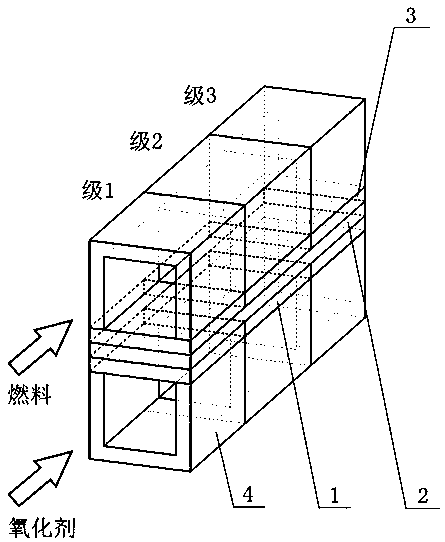
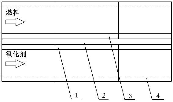
[0032] The invention is a multi-stage fuel cell structure. to attach figure 1 And attached figure 2 The schematic diagram of the single structure of the three-stage fuel cell stack in Fig. Taking a multi-stage fuel cell with a flow channel length of 10cm as an example (the size is only used for illustration), the multi-stage fuel cell is divided into three stages along the flow channel: stage 1 (3cm), stage 2 (4cm) and stage 3 (3cm). Wherein, the electrode collectors 4 of each level are independently insulated from each other. The stages of the anode 3 are independently insulated from each other. The cathode 1 stages are independently insulated from each other. The fuel and the oxidant respectively pass into the fuel channel and the oxidant channel of the multi-stage fuel cell. Take a multi-stage fuel cell with an ideal voltage of 1.2V as an example: on stage 1, stage 2, and stage 3, the discharge instrument (a kind of converter for fuel cell control, for illustration o...
Embodiment 2
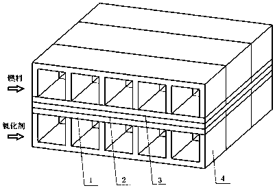
[0034] Such as image 3 Shown: In the transverse direction of a multi-stage fuel cell, five single cells form a stack (numbers are for illustration only). The monomers of five multistage fuel cells share the cathode 1 , the electrolyte membrane 2 , the anode 3 and the electrode collector 4 . The cell stack is divided into 3 levels in the flow channel direction: level 1, level 2 and level 3 (the number of levels is for illustration only). The electrode collectors 4 of each stage of the multi-stage fuel cell are electrically insulated from each other. The stages of the anode 3 are independently insulated from each other. The cathode 1 stages are independently insulated from each other. During the working process of the multi-stage fuel cell, the voltage of each stage is controlled by the discharge instrument (a kind of converter for fuel cell control, which is only used for illustration here), and decreases sequentially along the direction of the flow channel. The voltage is...
Embodiment 3
[0036] Such as Figure 4 Shown: In the longitudinal direction of multi-stage fuel cells, multiple cells form a fuel cell structure ( Figure 4 illustrated with two batteries). In the longitudinal direction, two adjacent fuel cell cells share the electrode collector 4 . The cell is divided into multiple stages in the direction of the fuel cell flow path ( Figure 4 The battery is divided into 3 levels for explanation). The battery stack anode 3 is divided into multiple stages along the direction of the flow channel. The battery stack cathode 1 is divided into multiple stages in the fuel cell direction. During the discharge process of the fuel cell stack, each stage of the battery stack controls the voltage through the discharge instrument (a kind of converter for fuel cell control, which is only used for illustration here), and the voltage is sequentially reduced along the direction of the flow channel. The voltage is converted into the required output voltage through a t...
PUM
 Abstract
Description
Claims
Application Information
 - R&D
- Intellectual Property
- Life Sciences
- Materials
- Tech Scout
- Unparalleled Data Quality
- Higher Quality Content
- 60% Fewer Hallucinations
Browse by: Latest US Patents, China's latest patents, Technical Efficacy Thesaurus, Application Domain, Technology Topic, Popular Technical Reports.
© 2025 PatSnap. All rights reserved.Legal|Privacy policy|Modern Slavery Act Transparency Statement|Sitemap|About US| Contact US: help@patsnap.com


